Cooling system and method for expelling heat from a heat source located in the interior of an aircraft

A cooling system and heat source technology, which is applied in aircraft galleys, aircraft parts, indirect heat exchangers, etc., can solve the problems of large weight, parasitic heat loss, and high maintenance cost of cooling systems, and achieve the effect of low weight

Inactive Publication Date: 2007-01-24
AIRBUS OPERATIONS GMBH
View PDF2 Cites 19 Cited by
  • Summary
  • Abstract
  • Description
  • Claims
  • Application Information

AI Technical Summary

Problems solved by technology

However, the disadvantage of these solutions is their relatively large weight
In addition, pumps are required to transfer the liquid heat transfer medium, which on the one hand leads to increased weight and on the other hand leads to parasitic heat losses which reduce the efficiency level of the cooling unit
Finally, this type of cooling system is relatively expensive to maintain

Method used


Image

  • Cooling system and method for expelling heat from a heat source located in the interior of an aircraft
  • Cooling system and method for expelling heat from a heat source located in the interior of an aircraft
  • Cooling system and method for expelling heat from a heat source located in the interior of an aircraft

Examples


Embodiment Construction

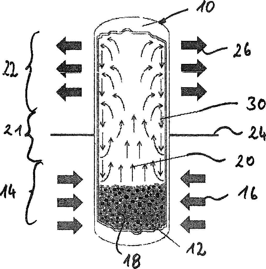
[0032] exist figure 1 A container in the form of a piping system for use with the cooling system according to the invention is shown in FIG. 1 , partly broken away and generally indicated by 10 . The container consists of a round cylindrical tube closed on all sides. In the lower part of the container, the heat transfer medium 12 is shown in liquid state.

[0033] The lower part 14 of the container 10 , which is referred to below as the heat input 14 , is in thermal contact with a heat source, whereby—as indicated by arrow 16 —heat from the heat source enters the heat input 14 of the container 10 . The heat shown by arrow 16 causes the heat transfer medium 12 to boil, as shown by bubbles 18 in the heat transfer medium 12, which eventually evaporates, as shown in figure 1 Indicated by the vertical upward pointing arrow 20.

[0034] Heat transfer medium vapor rises to the top of vessel 10 via transfer 21 and passes from heat sink 14 to heat output 22 whereby it passes through...


PUM


Abstract

A cooling system for removing heat from a heat source (38) located inside the aircraft to a radiator (32), having a piping system (10) sealed from the surrounding atmosphere, which is connected to an absorber carrying the heat source (38) The heat part (14) is thermally coupled to the heat output part (22) having a heat sink (32), and it preferably has a substantially insulated transfer part (21), the piping system (10) being filled with a heat transfer medium (12 ), when it absorbs heat from the heat source (38) in the heat absorbing part (14), the heat transfer medium undergoes a transition from a liquid to a gaseous state, and then flows into the heat output part (22), and there, when the heat is transferred to After discharge to the heat sink (32), it condenses again and flows back to the heat sink (14).

Description

technical field [0001] The invention relates to a cooling system for removing heat from a heat source located inside an aircraft to a radiator or heat sink. Background technique [0002] In an aircraft, especially a commercial aircraft, there are many electronic devices and other functional units that generate heat during operation of the aircraft. For example, food and beverages served in an aircraft's galley (kitchen) must be refrigerated so that they remain palatable after a sufficient period of time. Furthermore, there are many computer units inside the aircraft, which dissipate a lot of heat during their operation to ensure reliable functioning. [0003] In order to provide the above-mentioned cooling function, people have devised many ways in the past. For example, DE 38 12 739 shows a cooling system for cooling a refrigerated compartment in an aircraft. With this cooling system, it is proposed to convey air by means of a ventilator from the cold air chamber to the ...

Claims


Application Information

Patent Timeline
Patent Type & Authority Applications(China)
IPC IPC(8): F28D15/02B64D13/08B64D11/04
CPCB64D11/04F28D15/0266B64D2013/0629
Inventor 乔治·穆尔塔勒米夏埃尔·马克瓦特安德烈亚斯·埃多姆
Owner AIRBUS OPERATIONS GMBH
Why Eureka
Try Eureka