Lamp with double filament

A filament and lamp technology, which is applied to incandescent lamps, fixtures/supports of luminous bodies, electric heating devices, etc., can solve the problems of long and sagging incandescent bodies, and achieve the effect of reducing sagging and simplifying the manufacturing process.

Inactive Publication Date: 2007-01-24
KONINKLIJKE PHILIPS ELECTRONICS NV
View PDF2 Cites 2 Cited by
  • Summary
  • Abstract
  • Description
  • Claims
  • Application Information

AI Technical Summary

Problems solved by technology

However, the applicant has noticed that, in tube lamps such as described in US 2003 / 0001475, sagging of the incandescent body still occurs, especially when the tube lamp has been used for a relatively long period of time
Furthermore, the manufacture of such lamps is a long and complicated process, since it requires many steps of adding supports one by one around the incandescent body

Method used


Image

  • Lamp with double filament
  • Lamp with double filament
  • Lamp with double filament

Examples


Embodiment Construction

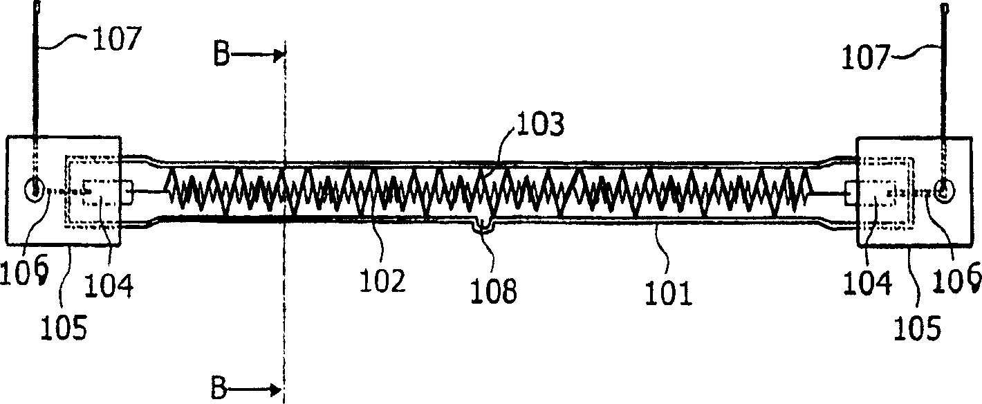
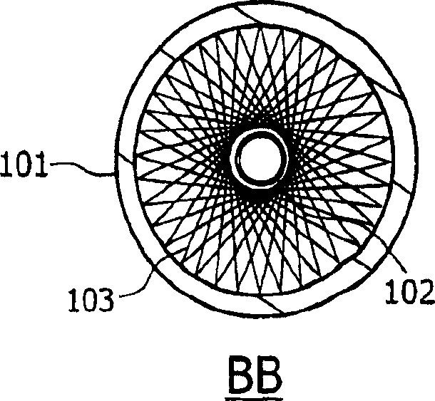
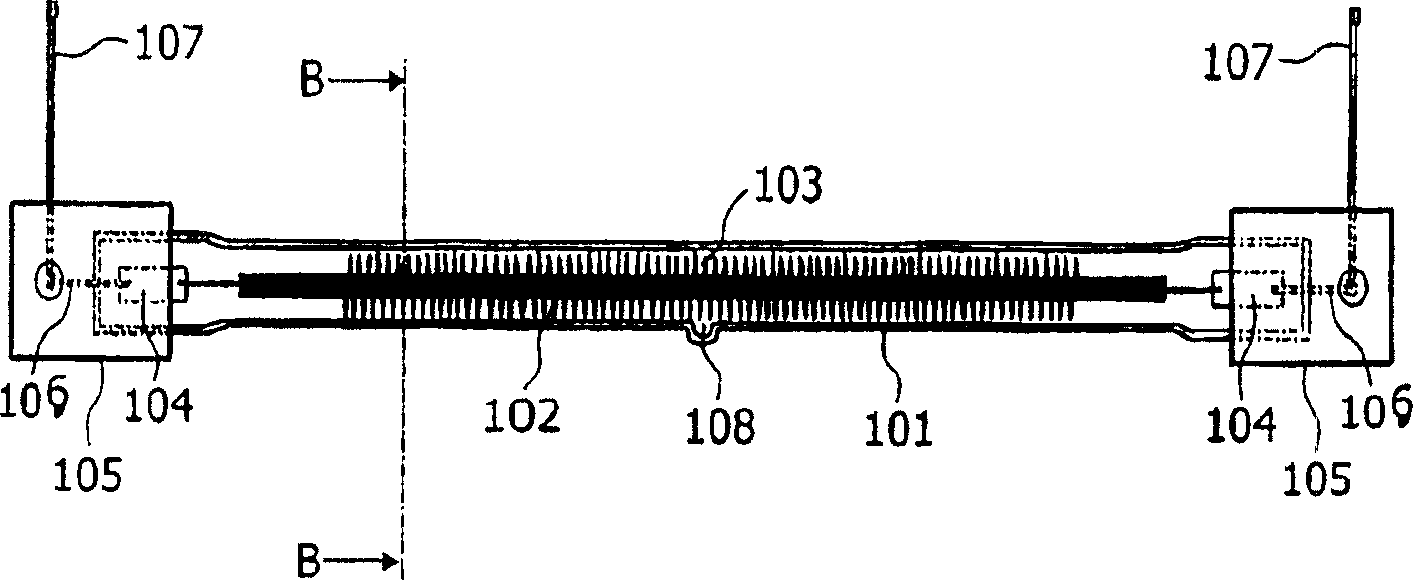
[0015] exist Figure 1a with 1b A lamp according to a first embodiment of the invention is described in . Figure 1b yes Figure 1a An enlarged cross-sectional view of the plane BB of . For ease of description, Figure 1a with 1b The individual dimensions of the parts on the lamp may not correspond. The lamp comprises a lamp tube 101 , an incandescent body 102 , a filament 103 and a power supply conductor 106 . The lamp also comprises a cover 105 , a foil 104 , a current wire 107 and a discharge tube 108 . Although already in Figure 1a A double-ended lamp is shown in , but the invention can also be applied to single-ended lamps.

[0016] The incandescent body 102 is, for example, a tungsten wire having an end connected to a foil 104, for example a molybdenum sheet, to which the end of the incandescent body 102 is welded. The supply conductor 106 is also soldered to the foil 104 . The supply conductor 106 is connected to a current line 107 . This can also be done by sol...


PUM


Abstract

The present invention relates to a lamp comprising a lamp vessel (101) having an inner diameter and an incandescent body (102) arranged in the lamp vessel and connected to current supply conductors (106). The lamp further comprises a filament (103) arranged around said incandescent body along at least half the length of said incandescent body, which filament has an outer diameter substantially equal to the inner diameter of the lamp vessel.

Description

technical field [0001] The present invention relates to tube lamps. [0002] The invention is applied, for example, to heating systems designed for industrial purposes, such as curing of synthetic resins by heating, drying of paper, baking of paint or semiconductor manufacturing. Background technique [0003] US patent US 2003 / 0001475 published on 2 January 2003 describes a tubular lamp comprising a lamp tube with an incandescent body arranged in the tube and connected to a supply conductor. To axially position the incandescent body within the tube, the tube lamp includes supports added around the incandescent body spaced along the length of the incandescent body. The supports reduce the sagging of the incandescent body, which can occur when the incandescent body is heated at relatively high temperatures. It is very important to reduce the sag of the incandescent body, because this sag shortens the service life of the tube lamp. However, the applicant has noticed that in ...

Claims


Application Information

Patent Timeline
Patent Type & Authority Applications(China)
IPC IPC(8): H01K1/24H01KH01K1/18H05B3/00
CPCH05B2203/032H01K1/18H05B3/0047H05B3/0066
Inventor E·格尤奎因
Owner KONINKLIJKE PHILIPS ELECTRONICS NV
Why Eureka
Try Eureka