Designing method of claw type rotor

A design method and rotor technology, applied to mechanical equipment, rotary piston pumps, rotary piston machines, etc., can solve problems such as noise and vibration, noise and vibration, and the tip 82, 92 is not smooth and smooth.

Active Publication Date: 2007-01-31
LIUNG FENG INDAL
View PDF8 Cites 10 Cited by
  • Summary
  • Abstract
  • Description
  • Claims
  • Application Information

AI Technical Summary

Problems solved by technology

[0002] Claw rotors applied to multi-stage compressors, vacuum pumps, air compressors or superchargers generally include: two meshing defined rotors and conjugate rotors, and the two rotors are respectively provided with meshing blades , through the two blades meshing with each other to provide a periodic cycle of intake and exhaust compression movement, therefore, the meshing of the two blades is very important, if the two blades mesh with each other poorly, in the periodic cycle of intake, exhaust, and non-compression Noise and vibration will be generated during the rotation process, and it will also cause friction between the two rotors due to improper meshing, which will reduce the service life
[0003] The structure of known related rotors can refer to US Patent Nos. 1,426,820, 4,138,848, 4,224,016, 4,324,538, 4,406,601, 4,430,050 and 5,149,256, etc., wherein the blades of the two rotors 8 and 9 of No. 5,149,256, such as Figure 8 As shown, peaks 82, 92 are formed at the junctions of concave portions 80, 90 and arc surfaces 81, 91, so that the curves of the entire rotor 80, 90 form a discontinuity at the peaks 82, 92. When compressed to the process of starting air intake, the top parts 83, 93 of the rotors 8, 9 will not run smoothly at the tip parts 82, 92, and there will be noise and vibration
In the same situation, in the aforementioned other U.S. patents, there is also the phenomenon of not running smoothly during the actuation process of the two meshing rotors, and there are noises and vibrations.

Method used


Image

  • Designing method of claw type rotor
  • Designing method of claw type rotor
  • Designing method of claw type rotor

Examples


Embodiment Construction

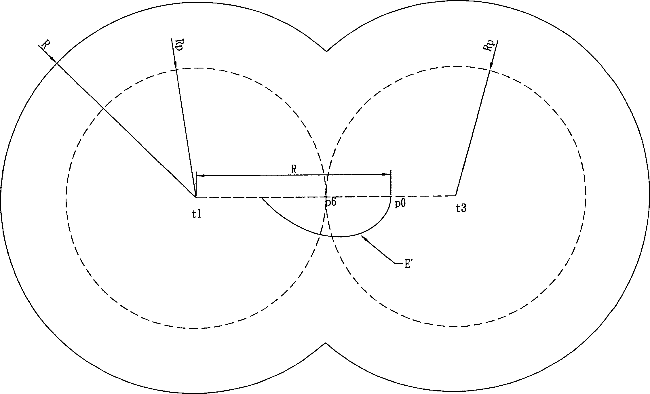
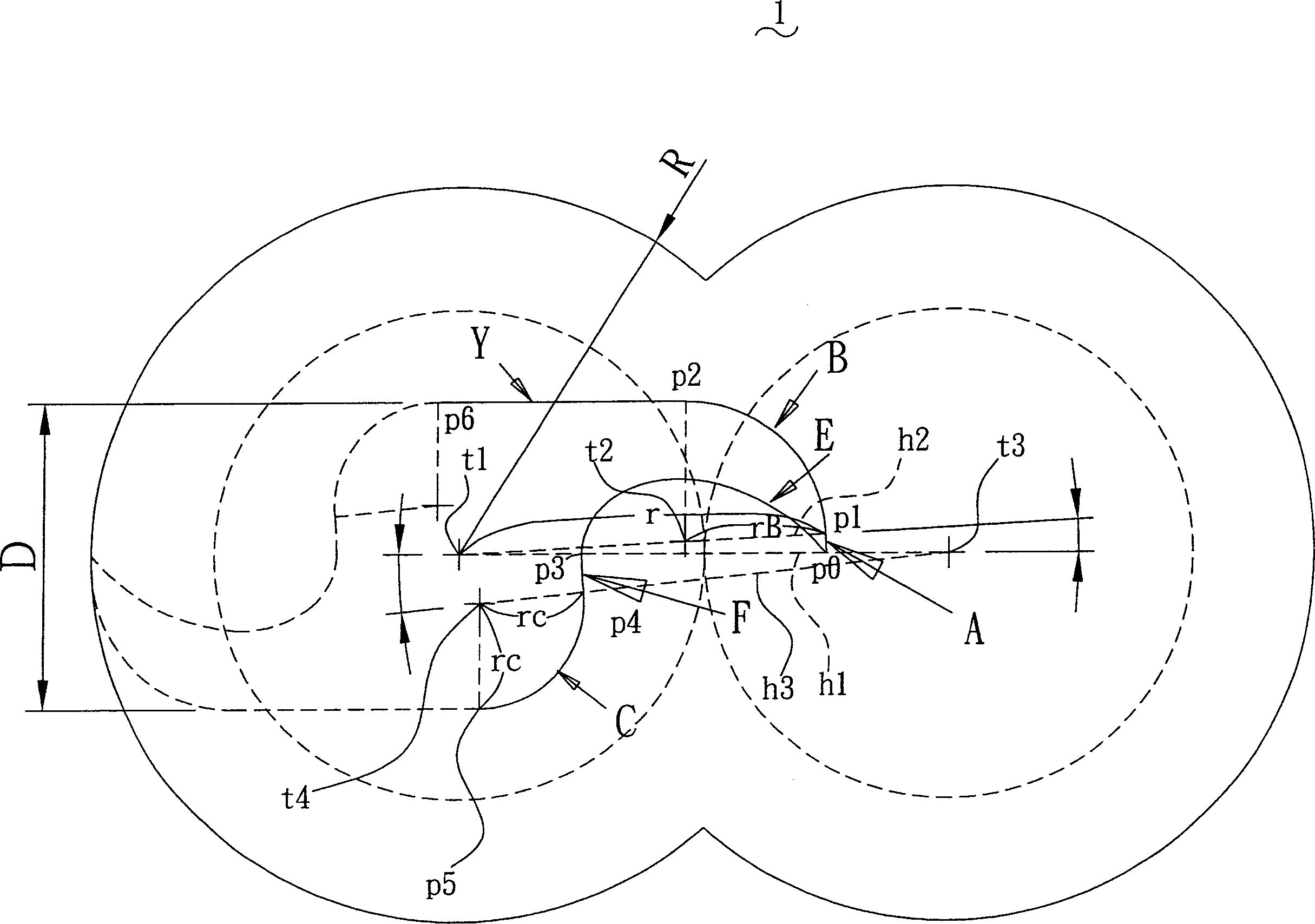
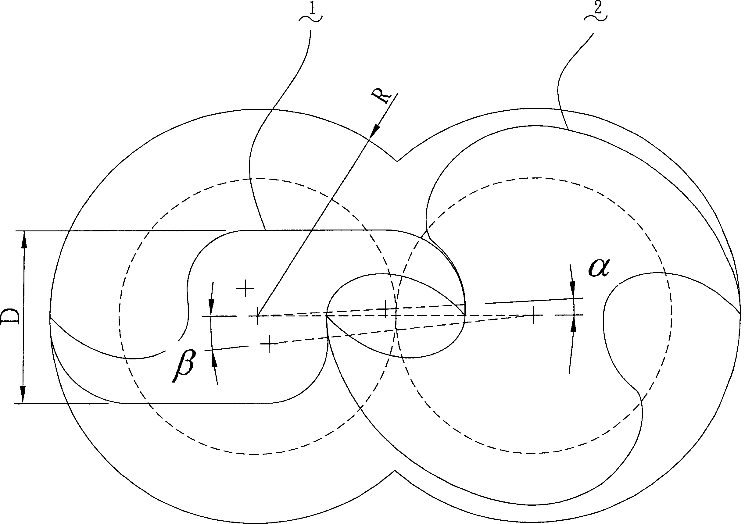
[0031] The claw rotor design method of the present invention is to obtain the shape of the defined rotor 1 first, and then obtain the shape of the conjugated rotor 2 with the conjugate curve, please refer to figure 1 , 2 , obtaining the shape of the defined rotor 1 includes the following steps:

[0032] 1. Define the maximum rotor radius R, define the rotor width D, define the pitch circle radius Rp of the rotor and the conjugate rotor, the centers of the two pitch circles are t1 and t2 respectively, Rp is less than R, and define the maximum rotor radius R and pitch The ratio of the circle radius Rp is R=3Rp / 2.

[0033] 2. Take the center t1 of the pitch circle as the center of the defined rotor, pass through a horizontal line h1, and obtain a point P on the horizontal line h1 0 , this point P 0 The horizontal distance of the circle center t1 is R, from this point P 0 A conjugate curve E' is generated around the center of the pitch circle t1, and the curve E' is relative ...


PUM


Abstract

There is disclosed a design method of claw rotors, which is used for designing defined rotors conjugate engaged each other and conjugate rotors. Taking the parameterization definition of the motion curvilinears of an ineffective compression to a beginning of the air-intaking and start to end of exhausting of two rotors estimates and seeks out the optimum performance of the rotor. When the rotor designed by the present invention is for use in a vacuum pump, a compressor, a supercharger and the like, it can provide a higher compression ratio and a transfer volume.

Description

technical field [0001] The present invention relates to a claw-type rotor design method, which is an additional patent application of Taiwan New Patent No. 220027 (compared to the Continuation In Part of US Patent No. 6,776,594; CIP). With the conjugate rotor, four parameters are used to define the motion curve of the two rotors from invalid compression to the beginning of intake, and the motion curve from the beginning to the end of exhaust, so as to evaluate and find the best rotor performance, which can be applied to vacuum pumps, air pressure Machines, compressors, superchargers, etc., to provide a higher compression ratio and delivery volume, and to make the intake and exhaust movement process smooth without noise and vibration. Background technique [0002] Claw rotors applied to multi-stage compressors, vacuum pumps, air compressors or superchargers generally include: two meshing defined rotors and conjugate rotors, and the two rotors are respectively provided with me...

Claims


Application Information

Patent Timeline
Patent Type & Authority Applications(China)
IPC IPC(8): F04C18/20
Inventor 钟添东林恒毅庄丰铭
Owner LIUNG FENG INDAL
Why Eureka
Try Eureka