Michelson's interferometer integrated into single optical fiber

A single optical fiber and interferometer technology is applied in the field of optoelectronics to achieve the effects of simplified and compact system, reduced volume and high stability

Inactive Publication Date: 2007-02-07
HARBIN ENG UNIV
View PDF1 Cites 32 Cited by
  • Summary
  • Abstract
  • Description
  • Claims
  • Application Information

AI Technical Summary

Problems solved by technology

However, in the case of high mechanical stability and temperature stability requirements for the interferometer, it is difficult for the fiber-optic Michelson interferometer composed of discrete optical structures to meet such requirements

Method used


Image

  • Michelson's interferometer integrated into single optical fiber
  • Michelson's interferometer integrated into single optical fiber
  • Michelson's interferometer integrated into single optical fiber

Examples


Embodiment Construction

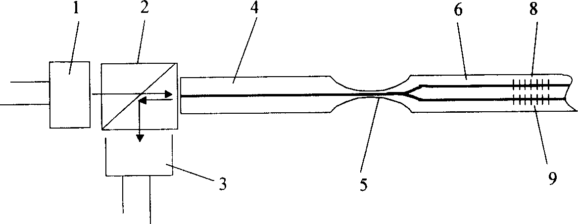
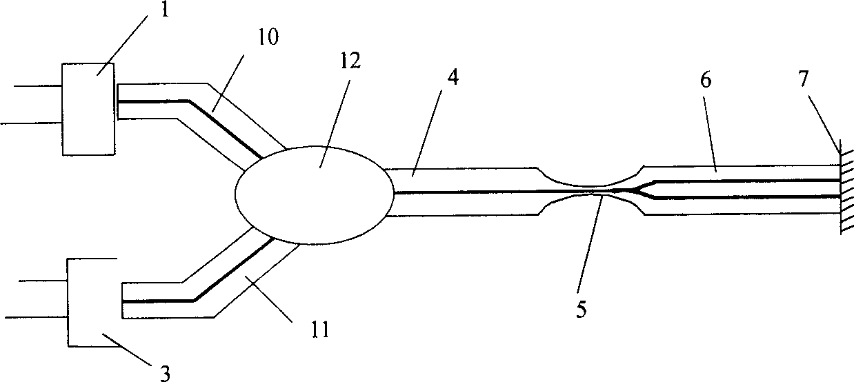
[0011] Three specific embodiments of the present invention are given below in conjunction with the drawings.

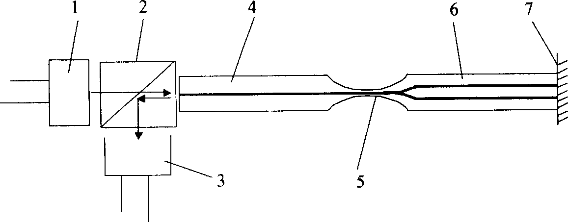
[0012] figure 1 The first specific embodiment of the present invention is shown. The Michelson interferometer integrated into a single fiber includes a light source 1, a micro-splitter 2, a light detector 3, a single-mode single-core fiber 4, a tapered coupling region 5, a single-mode twin-core fiber 6 and a mirror 7. Usually, the light source 1, the micro-splitter 2 and the photodetector 3 are combined into a light transmitting and receiving duplex device with pigtail.

[0013] The light source 1, the photodetector 3, the micro beam splitter 2 and the single-mode single-core fiber 4 are usually an independent duplex component. The single-mode single-core fiber 4 of the component is connected to a section of the single-mode dual-mode single-mode fiber whose end surface is plated with a mirror 7. The core optical fiber 6 is welded, and then the tapered coupling region 5 ...


PUM


Abstract

The related Michelson interferometer with only one optical fiber comprises: integrating the co-light-path part of source input and signal output and two interference arms into one optical fiber; and using the integrated optical fiber with one segment as mono-core fiber and one segment as dual-core fiber to replace the conventional product. The advantages of this invention include: 1. well stability; 2. small size and compact structure; 3. low requirement to source coherence; and 4. automatic compensation for light path difference.

Description

Technical field [0001] A Michelson interferometer integrated into a single optical fiber belongs to the field of optoelectronic technology. Background technique [0002] The usual fiber-optic Michelson interferometer is composed of two independent and separated fiber-optic interference arms. For example, Zhou Xiaojun and Liu Yongzhi's invention patent application "Fiber Michelson Interferometer with Optical Circulator" (Publication Number: CN 1444019A). In this interferometer, the light emitted by the light source is divided into two beams after passing through a 3dB 2×2 fiber coupler. They are respectively coupled to two independent fiber arms, and then reflected by the two fiber end reflectors. The original path is returned to the 2×2 fiber coupler to achieve interference, and the interference light signal is amplified after passing through the photoelectric conversion detector, thereby realizing the detection of the interference light signal. [0003] The above-mentioned inter...

Claims


Application Information

Patent Timeline
Patent Type & Authority Applications(China)
IPC IPC(8): G01B9/02
Inventor 苑立波杨军刘志海
Owner HARBIN ENG UNIV
Why Eureka
Try Eureka