Video imaging device with low radiation

An imaging device and low-radiation technology, applied in instruments, electrical digital data processing, electrical components, etc., can solve the problem of low electromagnetic radiation shielding effectiveness, and achieve the effect of solving electromagnetic coupling and avoiding hazards.

Inactive Publication Date: 2007-02-07
杨子刚 +1
View PDF0 Cites 6 Cited by
  • Summary
  • Abstract
  • Description
  • Claims
  • Application Information

AI Technical Summary

Problems solved by technology

[0004] An object of the present invention is to provide a low-radiation video imaging device to solve the proble

Method used


Image

  • Video imaging device with low radiation
  • Video imaging device with low radiation
  • Video imaging device with low radiation

Examples


Embodiment Construction

[0020] The present invention will be further described below in conjunction with the accompanying drawings and preferred embodiments.

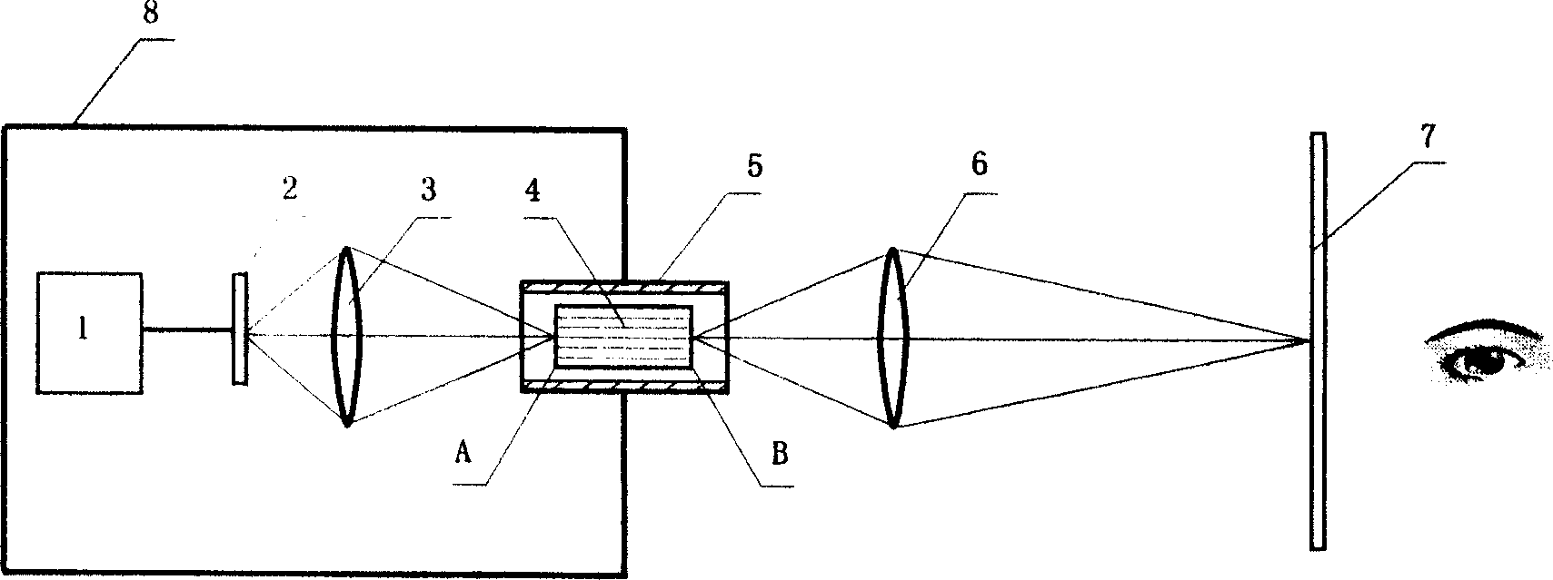
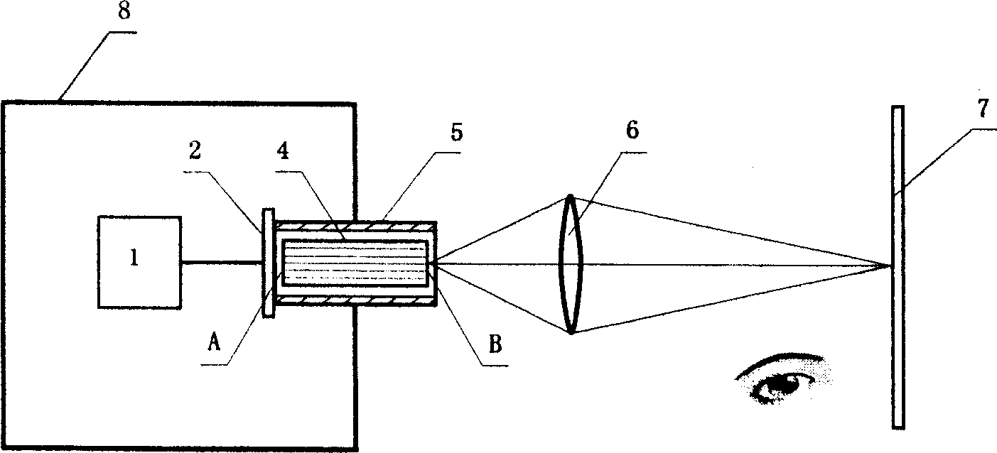
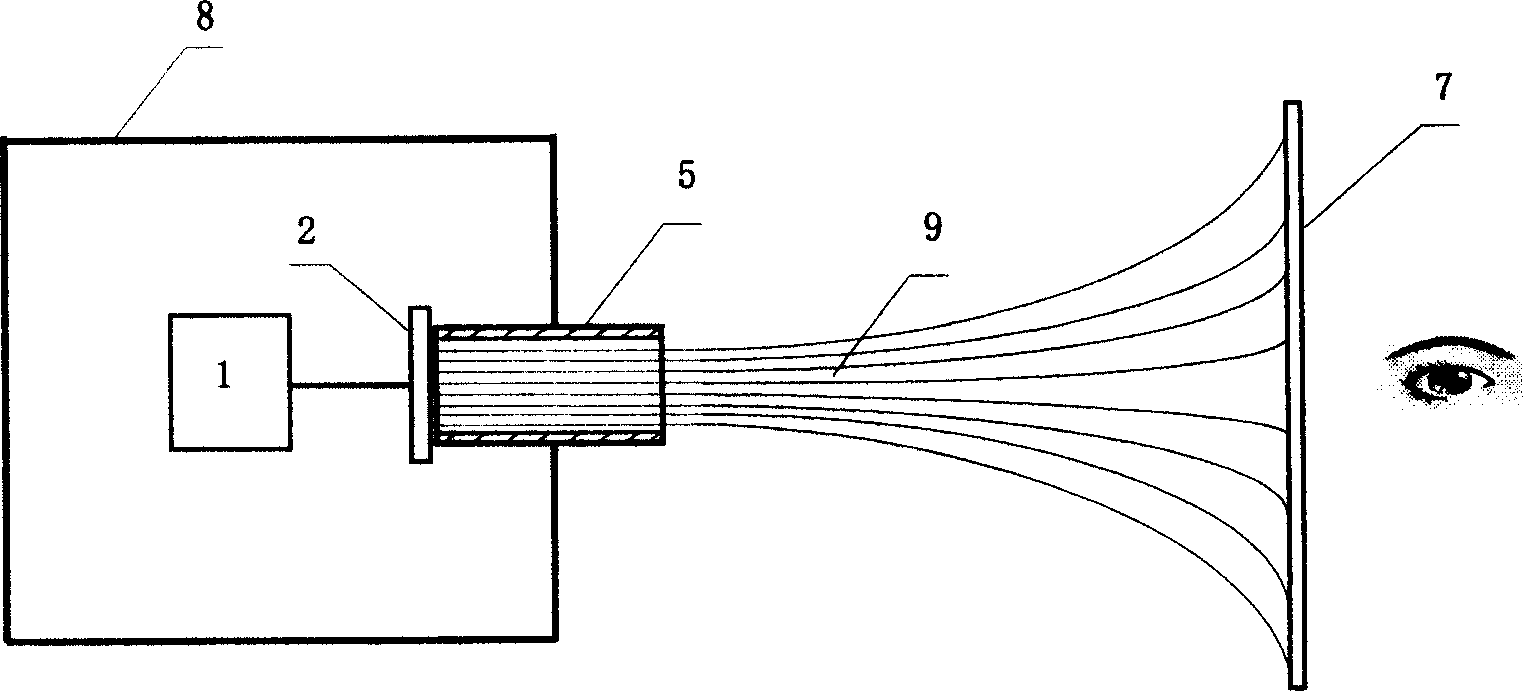
[0021] The system composition of a kind of preferred embodiment of the present invention is as figure 1 shown. In this embodiment, the low-radiation video imaging device includes an image source 1 , a display chip 2 , a front-end imaging objective lens 3 , an imaging fiber 4 , an electromagnetic wave cutoff tube 5 , a projection objective lens 6 , and a screen 7 . The electromagnetic wave cut-off tube 5 is installed in the through hole on the shield body 8, and the imaging optical fiber 4 is installed in the electromagnetic wave cut-off tube 5, wherein the electromagnetic wave cut-off tube 5 prevents the electromagnetic wave from passing through the shield body by utilizing the absorption and reflection attenuation of the electromagnetic wave by its tube wall In this embodiment, a circular waveguide is selected. The imaging fiber 4 is select...


PUM


Abstract

The disclosed low-radiation video imaging device comprises: an image source, a display chip, an imaging fiber, an EM-wave closure tube, and a screen, wherein it can convert video signal in shield body into optical signal to output outside through the imaging fiber arranged on a through-hole on the body, and recovers the image on outside screen by orthogonal or back projection. Unlike to traditional product, this invention can overcome the EM radiation efficiently, and can also be used for computer to prevent damage to people.

Description

technical field [0001] The invention relates to a video imaging device, in particular to a low-radiation video imaging device, and belongs to the technical fields of computer information security and electromagnetic shielding. Background technique [0002] At present, electromagnetic shielding equipment such as low-leakage monitoring consoles and electromagnetic shielding machine tables are widely used in secret-related departments of party, government, and military agencies. This kind of equipment generally arranges the display inside the shielding casing, and the user can watch the information on the display through the shielding glass window provided on the shielding casing. Due to the limitation of technical conditions such as materials and processes, the shielding effectiveness of shielding glass can only meet the requirements of Class B in the national confidentiality standard GGBB1-1999, which limits the improvement of the overall shielding effectiveness of electromag...

Claims


Application Information

Patent Timeline
IPC IPC(8): G02B6/24H05K9/00G06F1/00
Inventor 杨子刚郭林王冰于泳房非拉朱安东
Owner 杨子刚
Why Eureka
Try Eureka