Valve operating device for engine

An engine valve and transmission technology, which is applied to engine components, machines/engines, valve devices, etc., can solve the problems of unsatisfactory follow-up of engine valve opening and closing actions, and achieve good follow-up and easy positioning.

Inactive Publication Date: 2007-02-07
HONDA MOTOR CO LTD
View PDF2 Cites 6 Cited by
  • Summary
  • Abstract
  • Description
  • Claims
  • Application Information

AI Technical Summary

Problems solved by technology

[0003] However, in the valve train disclosed in Patent Document 1, it is necessary to secure a large space between the valve train cam and the rocker arm for arranging the link mechanism and the push rod, which increases the size of the valve train.
And because the driving force from the valve drive cam is transmitted to the rocker arm through the linkage mechanism and push rod, the followability of the rocker arm relative to the valve drive cam, that is, the followability of the opening and closing action of the engine valve is not ideal.

Method used


Image

  • Valve operating device for engine
  • Valve operating device for engine
  • Valve operating device for engine

Examples


Embodiment 1

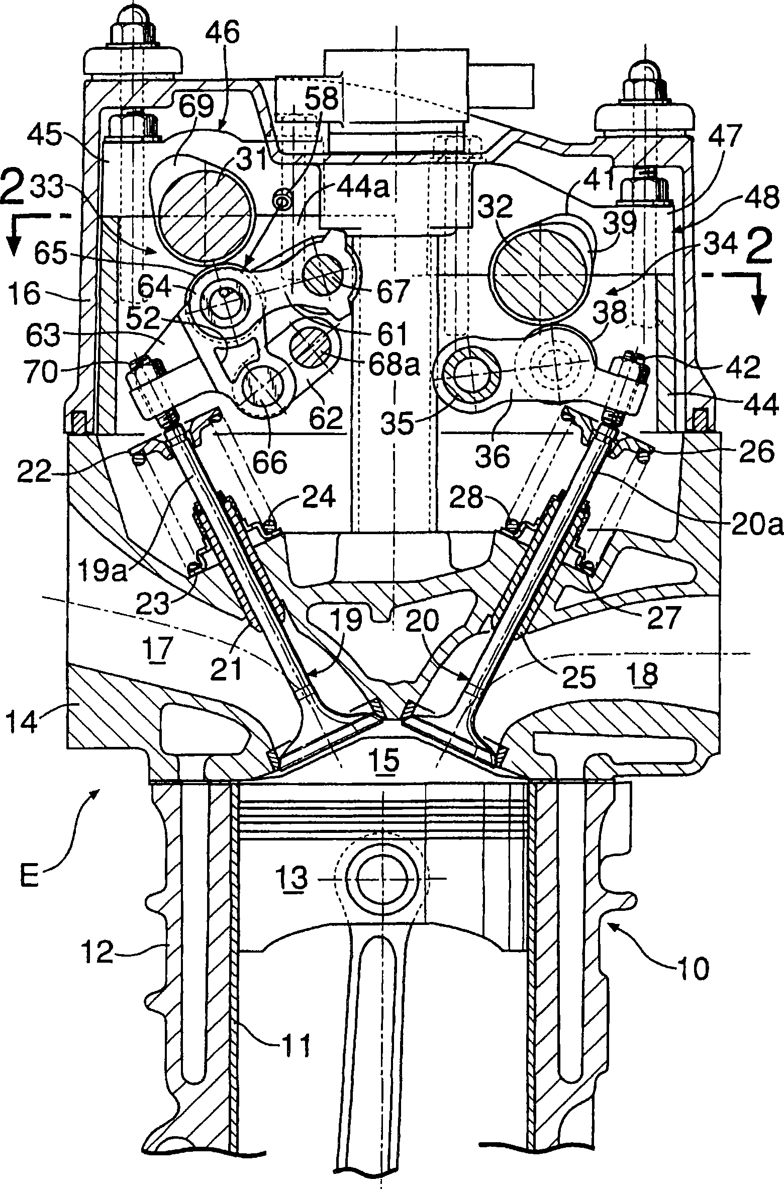
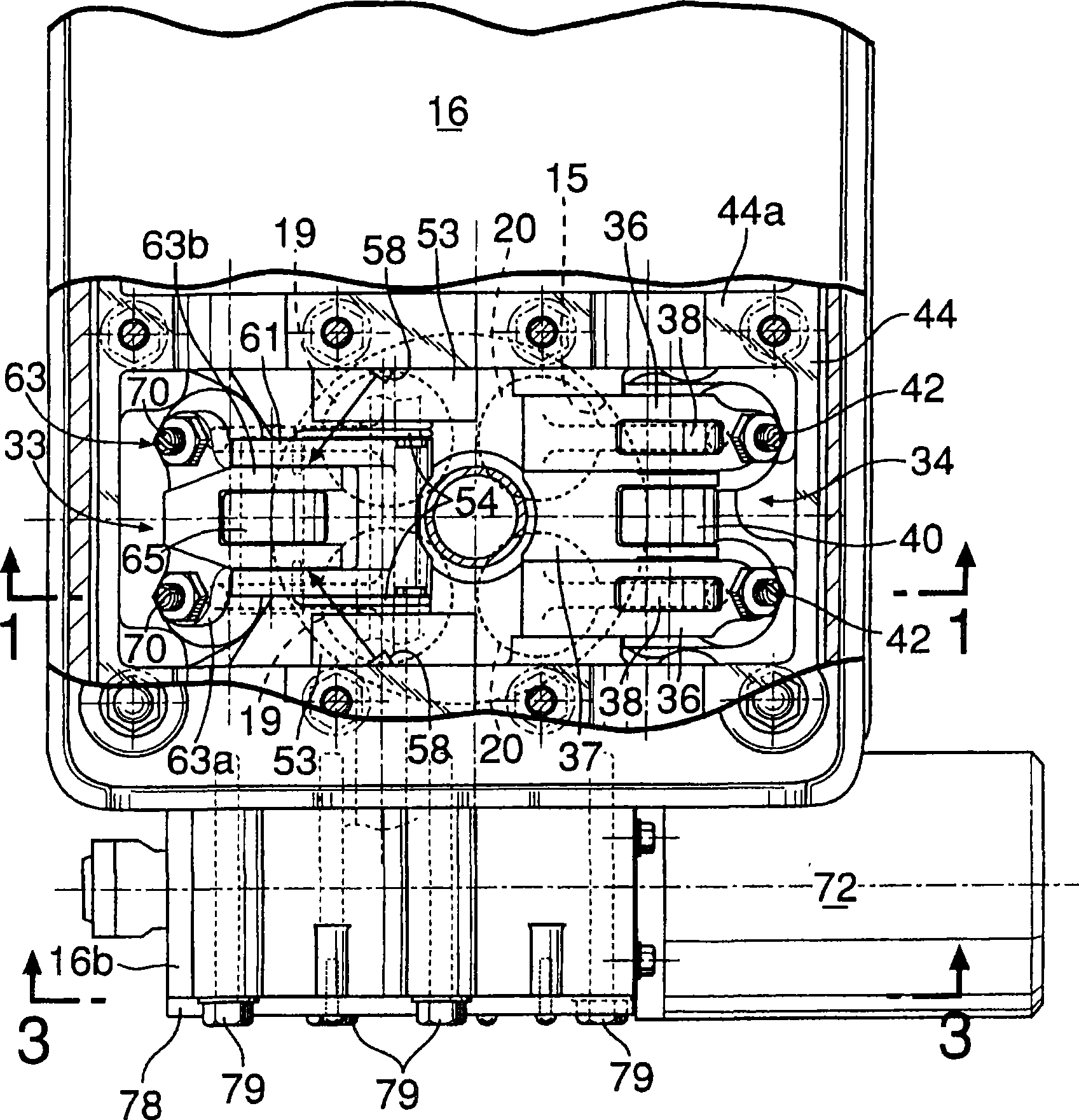
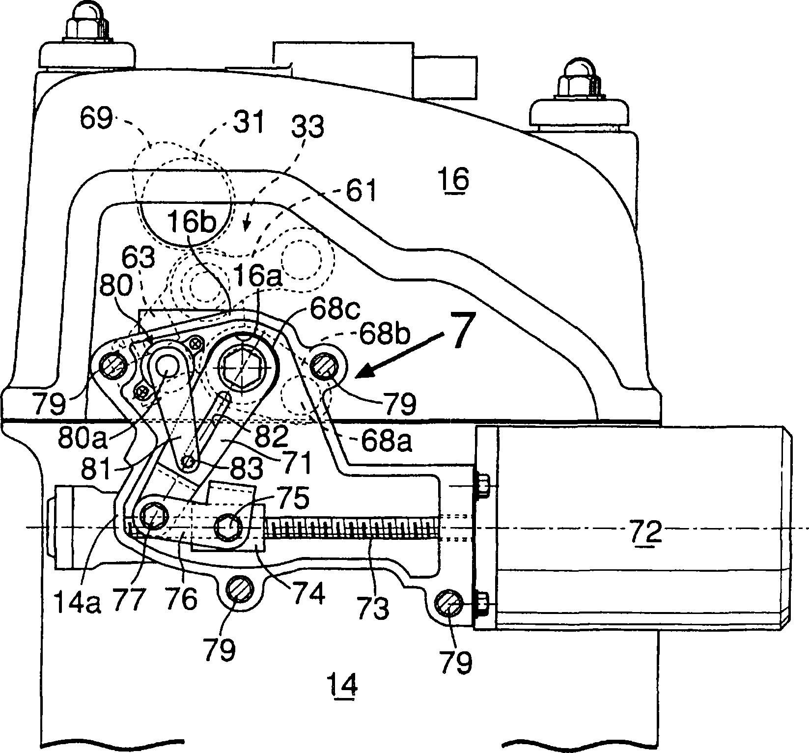
[0053] Figure 1 to Figure 11 Shows the first embodiment of the present invention.

[0054] first in figure 1 Among them, the engine body 10 of the in-line multi-cylinder engine E includes: a cylinder block 12, which is provided with a cylinder bore 11 inside; a cylinder head 14, which is joined with the top surface of the cylinder block 12; a cylinder head cover 16, which is connected to the cylinder head The top surface of 14 is joined, and in each cylinder bore 11 ..., piston 13 ... is slidably fitted, and the combustion chamber 15 ... facing the top of each piston 13 ... is formed between the cylinder block 12 and the cylinder head 14 .

[0055] On cylinder head 14, be provided with intake port 17 ... and exhaust port 18 ... that can communicate with each combustion chamber 15 ..., and each intake port 17 ... is respectively opened by a pair of intake valves 19 ... as engine valves. Each exhaust port 18 is opened and closed by a pair of exhaust valves 20... respectively...

Embodiment 2

[0106] Figure 12 to Figure 19 The second embodiment of the present invention is shown, and the same reference numerals are assigned to the parts corresponding to the above-mentioned first embodiment.

[0107] First, in Figure 12 to Figure 14 Among them, on the cylinder head 14, upper support members 98..., 100... are fastened as support walls in a manner arranged on both sides of each cylinder, and end covers 99..., 100... are fastened to each upper support member 98... from above, The end caps 99 . . . , 100 . . . together form an intake-side cam support 101 . Furthermore, the intake camshaft 31 is rotatably supported between the upper support member 98... constituting the intake side cam support member 101 and the end cover 99, and the upper support member 98 constituting the exhaust side cam support member 102... ... and the end cover 100 ... is rotatably supported by an exhaust camshaft 103 .

[0108]The exhaust side rocker shaft 104 is supported by the upper support ...


PUM


Abstract

A rocker arm (63) is provided with a valve connecting portion (63a) into which tappet screws (70) abutting against a pair of engine valves (19) are screwed so that their advance / retract positions can be adjusted, and the rocker arm (63) has a cam abutting portion (65) which abuts against a valve operating cam (69) and is interlocked and connected to the engine valves (19). The rocker arm (63) turnably connects to one end of a first link arm (61) turnably supported at a fixed position of an engine body and to one end of a second link arm turnably supported by a displaceable movable support shaft (68a). The rocker arm (63) is formed so that the valve connecting portion (63a) has a larger width in a direction along a rotating axis of the valve operating cam (69) than in the remaining part. This enables the lift amount of the engine valves to be continuously varied. It is also possible to reduce the size of the system, while ensuring follow-up ability of the opening / closing operations.

Description

technical field [0001] The present invention relates to a valve train for an engine, which has a variable lift mechanism for continuously changing the lift amount of an engine valve as an intake valve or an exhaust valve. Background technique [0002] In order to continuously change the lift of the engine valves, Patent Document 1 discloses a valve train that has a valve abutting portion that abuts against the engine valve on one end side of the rocker arm, and has a valve abutting portion on the other end of the rocker arm. One end of a push rod is fitted to one end, and a link mechanism is provided between the other end of the push rod and the valve driving cam. [0003] However, in the valve train disclosed in Patent Document 1, it is necessary to ensure a large space between the valve train cam and the rocker arm for arranging the link mechanism and the push rod, which increases the size of the valve train. And because the driving force from the valve driving cam is tra...

Claims


Application Information

Patent Timeline
Patent Type & Authority Applications(China)
IPC IPC(8): F01L13/00F01L1/18
Inventor 藤井德明中村胜则米川明之藤本智也吉田惠子
Owner HONDA MOTOR CO LTD
Why Eureka
Try Eureka