Reflector and backlight device

A technology of backlight device and reflector, applied in the field of backlight device and reflector, can solve the problem of insufficient light distribution and achieve the effect of high uniformity

Inactive Publication Date: 2007-02-07
HITACHI CHEM CO LTD
View PDF0 Cites 40 Cited by
  • Summary
  • Abstract
  • Description
  • Claims
  • Application Information

AI Technical Summary

Problems solved by technology

[0009] In the prior art, although the light emitted from the light source 2 enters the light guide plate 1 from the incident surface 5, near the incident surface 5 of the light guide plate 1, the light from the diode point light source spreads out in a fan shape and passes through the light guide plate. Transmission within 1, because it is a point light source, it will produce dark parts between light source 2
[0010] In addition, the light from the light source 2 tends to generate hot spots, glow lines, etc. called pulsating shading and cat's-eye phenomenon (mudama phenomenon) cause

Method used


Image

  • Reflector and backlight device
  • Reflector and backlight device
  • Reflector and backlight device

Examples


Embodiment Construction

[0037] Next, embodiments of the reflector and the backlight device of the present invention will be described in detail with reference to the drawings.

[0038] In this embodiment, for the sake of simplicity, the same components are denoted by the same reference symbols in several different drawings. In addition, the drawings of this embodiment are used for explaining the content of the present invention, and do not accurately reflect the ratio of the dimensions of each part.

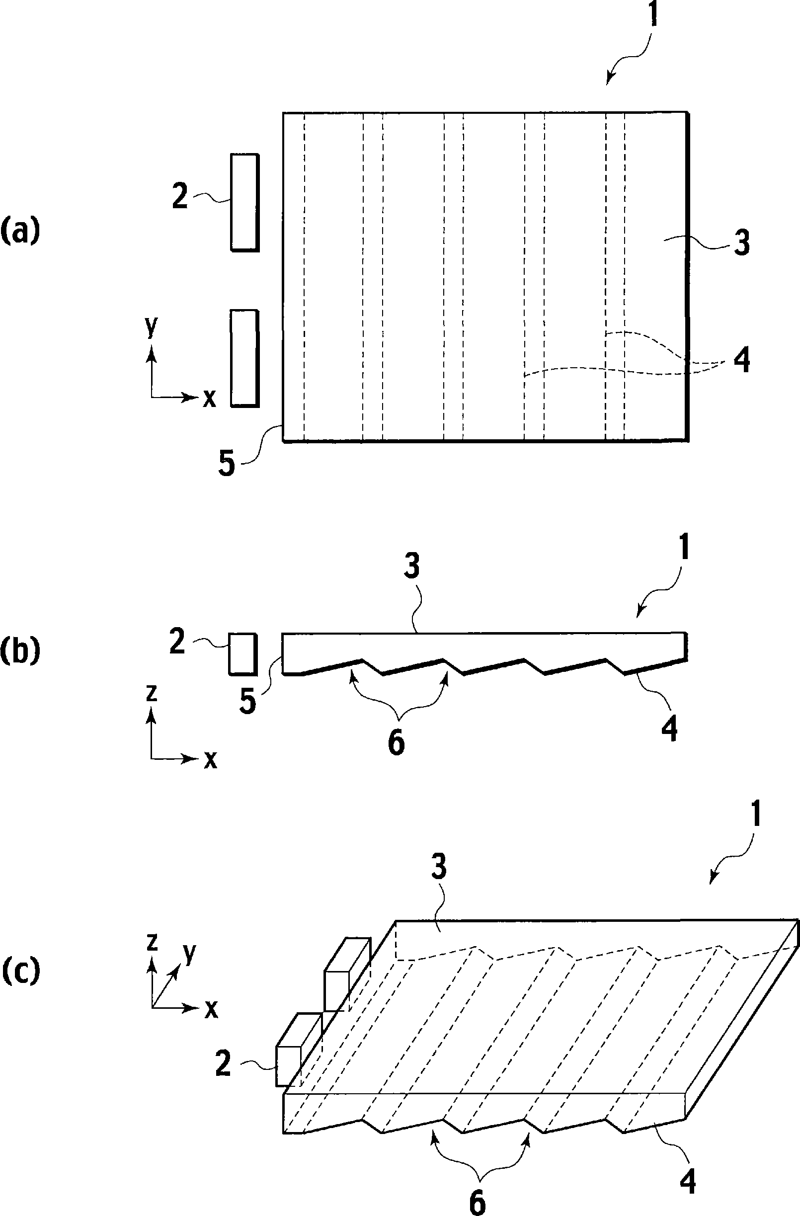
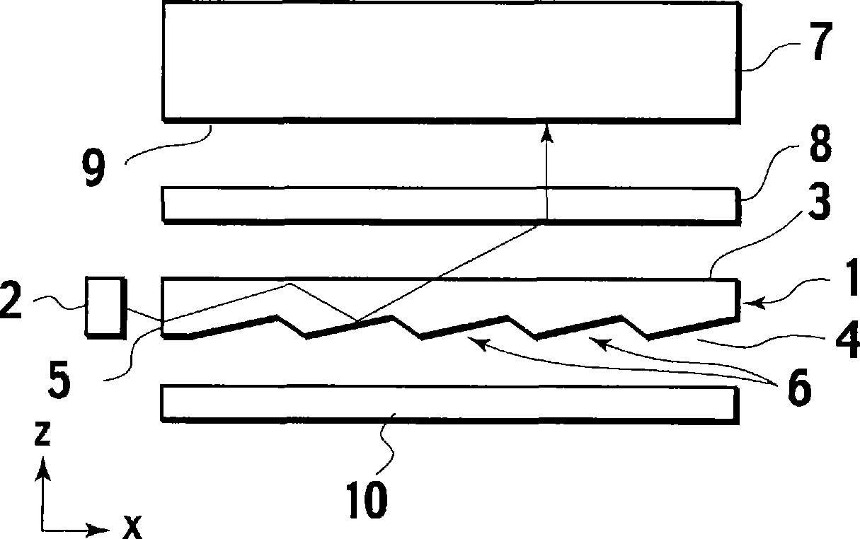
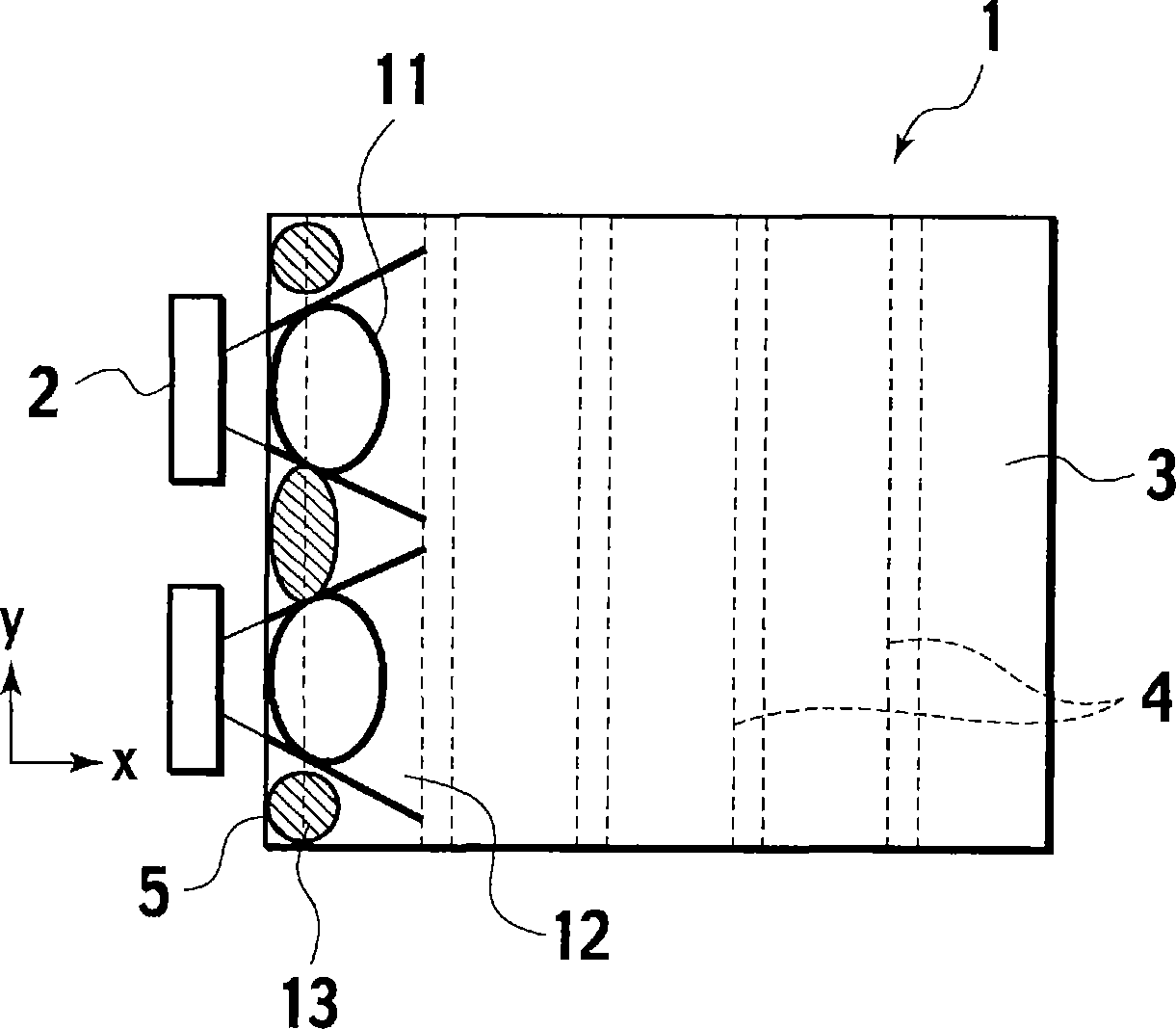
[0039] In addition, for convenience of reference, an xyz rectangular coordinate system is set in the figure. The x-axis and the y-axis are set along the two upper and lower sides of the light guide plate in the light traveling direction of the light guide plate, and the z-axis is set along the normal direction of the emitting surface. In addition, the positive and negative directions of the z axis are referred to as up and down.

[0040] Figure 4 is a reflector showing the first embodiment. Figure...


PUM


Abstract

A back light device realizing improvement in hotspots and bright line in the region of light incidence and of darkness arising in between light sources is provided by forming the reflective surface of the reflector as a structured face comprising an iteration of prism elements of trapezoidal section.

Description

technical field [0001] The invention relates to a reflector and a backlight device using the reflector. Background technique [0002] In the prior art, there is provided a method for guiding light emitted from a light source to a light guide plate of a liquid crystal display device for illuminating a liquid crystal display device such as a mobile phone, and for illuminating a liquid crystal display device having the light guide plate from the back. backlight unit. [0003] figure 1 It is a perspective view showing the appearance of a conventional light guide plate. In the illustration, a light emitting diode 2 as a light source is also shown at the same time. The light guide plate 1 is made of a transparent material such as PMMA or polycarbonate, and has a substantially plate-like flat shape. In addition, the upper surface and the lower surface are used as the emission surface 3 and the reflection surface 4 , respectively, and one side surface is used as the incident sur...

Claims


Application Information

Patent Timeline
IPC IPC(8): F21V8/00G02B5/08G02F1/13357F21Y101/02G02B5/09G02F1/1335
CPCG02B5/09G02F1/1335
Inventor 杉本靖手岛照雄
Owner HITACHI CHEM CO LTD
Why Eureka
Try Eureka