Heat pipe and manufacturing method thereof

一种制造方法、热管的技术,应用在间接换热器、照明和加热设备等方向

Inactive Publication Date: 2007-02-14
FU ZHUN PRECISION IND SHENZHEN +1
View PDF0 Cites 15 Cited by
  • Summary
  • Abstract
  • Description
  • Claims
  • Application Information

AI Technical Summary

Problems solved by technology

[0011] In order to improve the permeability of the condensed liquid in the capillary structure of the condensation part and solve the problem of the mandrel stripping during the sintering process, it is necessary to provide a heat pipe with the advantages of high capillary pressure and high permeability, and provide a heat pipe that can Heat pipe manufacturing method to solve the problem of mandrel stripping

Method used


Image

  • Heat pipe and manufacturing method thereof
  • Heat pipe and manufacturing method thereof
  • Heat pipe and manufacturing method thereof

Examples


Embodiment Construction

[0025] Figure 4 It is a flow chart of a preferred manufacturing process of the heat pipe of the present invention, which is to first set a screen 20 on the outer surface of a mandrel 10, and then insert this combined component into a heat-conducting shell 30, such as Figure 5 and Image 6 shown. Of course, in this step, the mandrel 10 can also be inserted into the heat-conducting housing 30 first, and then the screen 20 is bonded to the outer surface of the mandrel 10. An operation mode in which the rod 10 is combined with the screen 20 and then inserted into the heat conduction housing 30 .

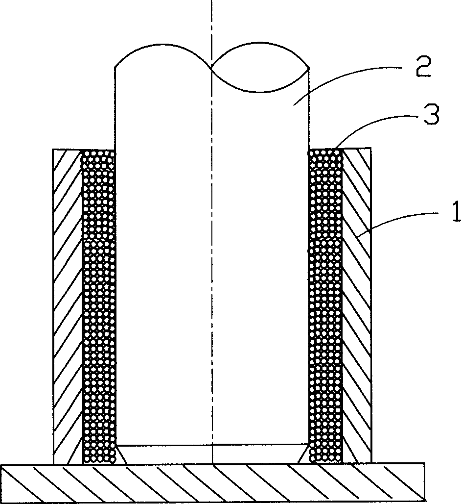
[0026] Next, fill the fine powder 40 of appropriate density in the gap between the inner wall of the heat conduction shell 30 and the screen 20, in order to facilitate the positioning of the mandrel 10 and prevent the filled powder 40 from leaking out, the bottom of the heat conduction shell 30 The end 31 can be pre-formed into a neck shape, such as Figure 5 As shown, the mandrel ...


PUM


Abstract

A heat pipe consists of a heat conduction shell and a capillary structure. Its preparing method includes setting capillary structure in said shell, forming capillary structure by superposing screen mesh layer with particle layer, combining core bar surface with screen mesh, inserting core bar into said shell then filling micro powder in gas between said shell and screen mesh and sintering it with high temperature for obtaining product of heat pipe.

Description

【Technical field】 [0001] The invention relates to a heat pipe for heat transfer using the principle of phase change and a manufacturing method thereof. 【Background technique】 [0002] Due to its small size, the use of phase change latent heat to quickly transport a large amount of heat energy, uniform temperature distribution, simple structure, light weight, no external force, long life, low thermal resistance, long-distance transmission and other characteristics, the heat pipe meets the current heat dissipation requirements of the computer and other fields , so it is widely used to solve the heat dissipation problem. [0003] The driving principle of the heat pipe is to use the saturated working fluid contained in the capillary structure of the evaporation part to absorb the heat of the external heat source and evaporate. Due to the pressure difference generated by the steam, the steam moves quickly to the condensation part of the heat pipe and transfers heat, and finally c...

Claims


Application Information

Patent Timeline
Patent Type & Authority Applications(China)
IPC IPC(8): F28D15/04
CPCB23P15/26B23P2700/09F28D15/046F28D15/0283Y10T29/53113Y10T29/49353Y10T29/49377
Inventor 侯春树童兆年刘泰健杨志豪谢国柱
Owner FU ZHUN PRECISION IND SHENZHEN
Why Eureka
Try Eureka