Tension line video deflection measuring device and method

A technology of deflection measurement and tension line, which is applied in the direction of measuring devices, optical devices, elastic testing, etc., can solve the problems of low measurement accuracy, increased measurement cost, complex calculation errors, etc., and achieves convenient transmission and processing, convenient installation and debugging, Effects that are cheap to manufacture

Inactive Publication Date: 2007-02-14
CHONGQING JIAOTONG UNIVERSITY
View PDF3 Cites 17 Cited by
  • Summary
  • Abstract
  • Description
  • Claims
  • Application Information

AI Technical Summary

Problems solved by technology

For example, the "displacement/deflection detection and monitoring device and method" disclosed in Chinese patent 200310057473.6 and the "multi-point dynamic deflection/displacement measurement device with self-calibration and self-encoding imaging method" disclosed in Chinese patent 200510020324.2, the former uses one-to-one measurement and cannot be used One camera shoots and measures multiple targets, which greatly increases the cost of measurement; the latter has low measurement accuracy due to its wide measurement range and cannot meet the high-precision requirements
Another example is that the detection of bridge deflection by the photoelectric liquid connecting pipe method is greatly affected by temperature, and the calculation error is complicated
Another example is the 200510020375.5 "two-dimensional, large-scale laser deflection/displacement measurement method and device" disclosed in the Chinese patent. By controlling the controllable damping hinge structure, the laser beam reflecting the position of t...

Method used


Image

  • Tension line video deflection measuring device and method
  • Tension line video deflection measuring device and method
  • Tension line video deflection measuring device and method

Examples


Embodiment Construction

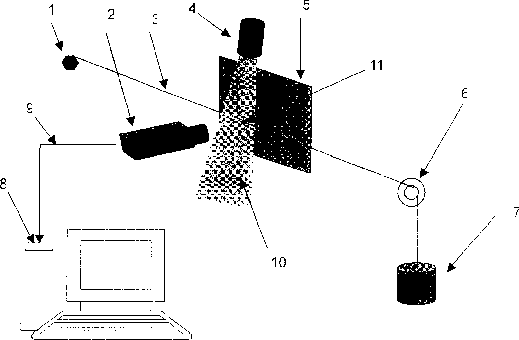
[0024] Such as figure 1 As shown, the tension line video deflection measurement method of the present invention, the main device is an imaging device 2 connected with a computer 8; an assembly composed of a fixed bolt 1, a fixed pulley 6, a weight 7 and a tension line 3; and a linear laser 4 and The background screens 5 and 9 are connection lines. During installation, fix the fixed bolt 1 and the fixed pulley 6 to appropriate positions on the bridge piers on both sides of the bridge, one side of the tension line 3 is fixed on the fixed bolt 1, and the other side bypasses the fixed pulley 6 and connects with the weight 7. Make the tension line 3 in a taut state. The camera device 2 is fixed at the point to be measured in the middle of the bridge span, the lens end faces the tension line 3, and the background screen 5 is placed behind the tension line 3, so that the camera device 2 can only record the tension line 3 and the background screen 5. The linear laser 4 is installed ...


PUM


Abstract

A method for measuring video deflection of tension line includes erecting fixed bolt and fixed pulley on piers at two sides of bridge, connecting two ends of tension line separately to said bolt and weight to make tension line be tightened, erecting video camera at position to be measured on bridge to let shooting tube right-point to tension line, moving video camera up and down to vary position of fixed light point of laser on tension line in image of video camera, collecting and calculating position of light point in image for obtaining deflection of bridge. The device for realizing said method is also disclosed.

Description

technical field [0001] The invention relates to a device and method for detecting and monitoring bridge deflection, which can also be used for detection and monitoring of ground subsidence, mountain movement, building subsidence, etc., especially a method for on-line monitoring of deflection using tension lines, lasers and video systems. Background technique [0002] Detecting bridge deflection plays an important role in modern road and bridge health detection and monitoring. In the prior art, there are more and more methods and devices for detecting and monitoring bridge deflection. Although the functions are the same, the structures are different. For example, the "displacement / deflection detection and monitoring device and method" disclosed in Chinese patent 200310057473.6 and the "multi-point dynamic deflection / displacement measurement device with self-calibration and self-encoding imaging method" disclosed in Chinese patent 200510020324.2, the former uses one-to-one mea...

Claims


Application Information

Patent Timeline
IPC IPC(8): G01B11/00G01B11/02G01M5/00
Inventor 蓝章礼张奔牛杨小帆
Owner CHONGQING JIAOTONG UNIVERSITY
Why Eureka
Try Eureka