Coupling two-way linear ultrasonic electric machine of changer and its exciting method

An ultrasonic motor and transducer technology, applied in the directions of generators/motors, piezoelectric effect/electrostrictive or magnetostrictive motors, electrical components, etc., can solve the problem that curved linear ultrasonic motors are not easy to move in both directions, excitation Single method, small output power and other problems, to achieve the effect of large thrust, high power, and large output force

Inactive Publication Date: 2007-02-14
HARBIN INST OF TECH
View PDF0 Cites 6 Cited by
  • Summary
  • Abstract
  • Description
  • Claims
  • Application Information

AI Technical Summary

Problems solved by technology

[0003] The object of the present invention is to provide a transducer-coupled bidirectional linear ultrasonic motor and its excitation method, which can solve the problems of small amplitude and low driving force in bending linear ultrasonic motors, Π-type linear ultrasonic motors and longitudinal bending composite linear ultrasonic motors. Large, low output power, single excitation method and bending linear ultrasonic motor is not easy to achieve two-way motion, poor control performance

Method used


Image

  • Coupling two-way linear ultrasonic electric machine of changer and its exciting method
  • Coupling two-way linear ultrasonic electric machine of changer and its exciting method
  • Coupling two-way linear ultrasonic electric machine of changer and its exciting method

Examples


specific Embodiment approach 1

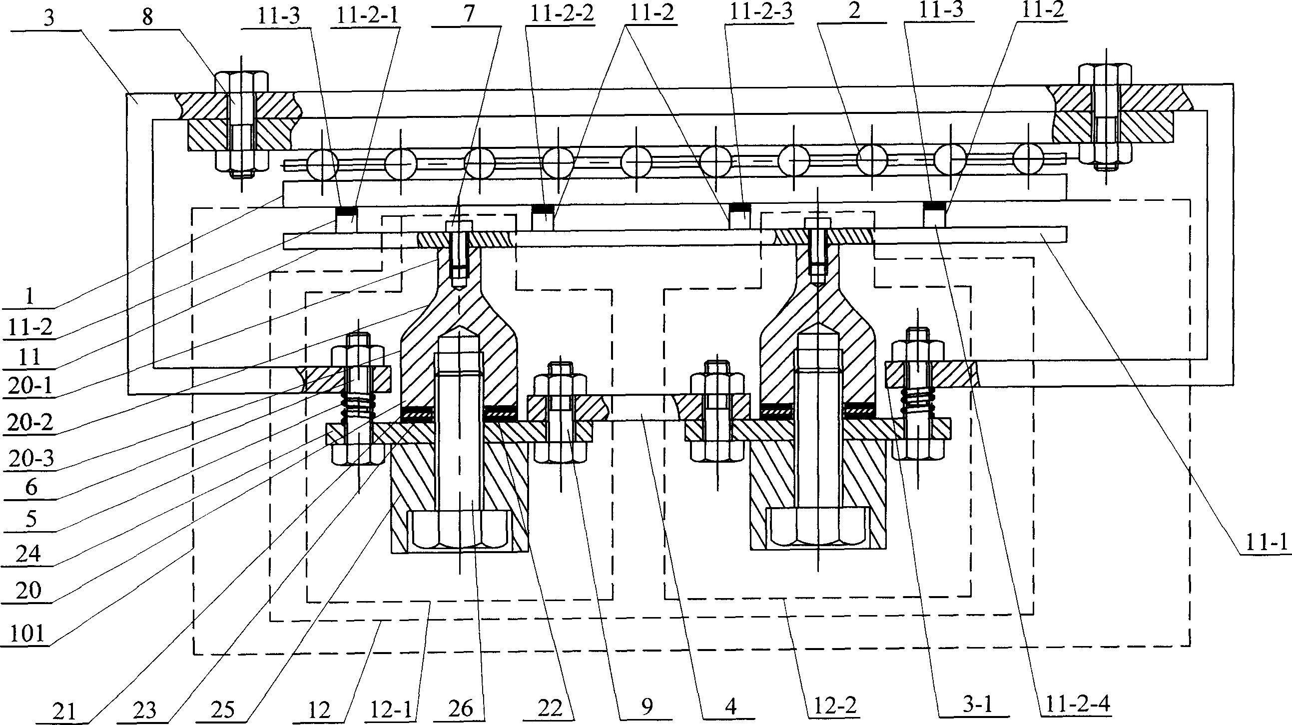
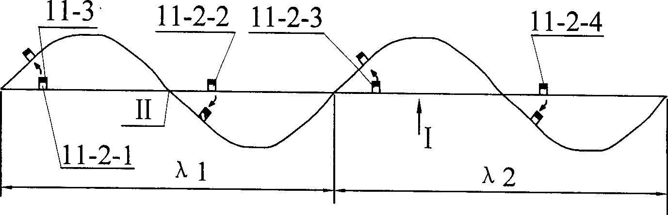
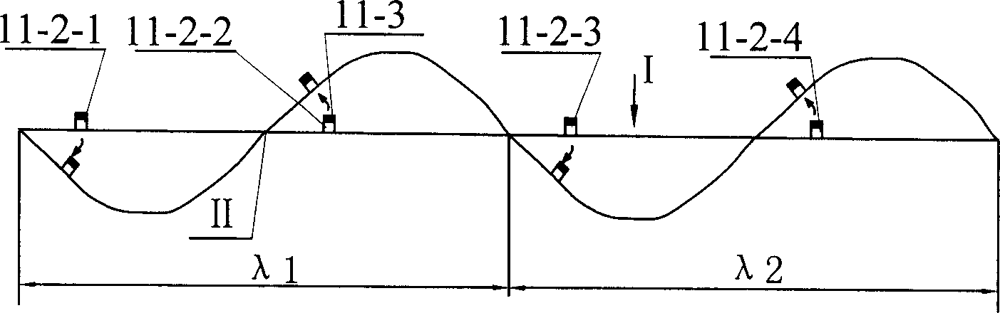
[0007] Specific implementation mode one: combine figure 1 Describe this embodiment, this embodiment is composed of mover 1, stator 101, linear bearing 2, bracket 3, connecting plate 4, elastic loading device 5, connecting bolt 6, screw one 7, bolt one 8, and bolt two 9; The stator 101 is composed of a gear plate 11 and a Lanwenjie transducer vibrator 12, and the gear plate 11 is composed of a base plate 11-1, teeth 11-2 and friction layer 11-3; The teeth 11-2 are sequentially fixed on the base plate 11-1 from left to right by the first gear 11-2-1, the second gear 11-2-2, the third gear 11-2-3 and the fourth gear 11- Composed of 2-4; the first gear 11-2-1 is set at 1 / 8λ1 or 3 / 8λ1 of the first wavelength λ1 of the standing wave formed by the substrate 11-1, and the second gear 11-2-2 is set on the substrate 5 / 8λ1 or 7 / 8λ1 of the first wavelength λ1 of the standing wave formed by 11-1; the third gear 11-2-3 is set at 1 / 2 of the second wavelength λ2 of the standing wave formed b...

specific Embodiment approach 2

[0009] Specific implementation mode two: combination figure 1 To illustrate this embodiment, the first transducer vibrator 12-1 and the second transducer vibrator 12-2 of this embodiment are respectively composed of the front matching block 20, the first piezoelectric ceramic sheet 21, the thin copper sheet 22, and the second piezoelectric ceramic sheet. 23. The flange 24, the rear matching block 25 and the screw 26 are composed; the front matching block 20 is made of aluminum, steel, copper or titanium alloy, and the rear matching block 25 is made of aluminum, titanium alloy, steel or copper. The front matching block 20 is composed of an integrated small cylinder 20-1, a curved transition body 20-2 and a large cylinder 20-3 from front to back. Such design has better energy gathering effect and driving efficiency. High; transducer vibrator 1 12-1 and transducer vibrator 2 12-2 are provided with front matching block 20, piezoelectric ceramic sheet 1 21, thin copper sheet 22, pi...

specific Embodiment approach 3

[0010] Specific implementation mode three: the excitation method of the transducer coupling bidirectional linear ultrasonic motor of the present embodiment is completed in this way: the excitation mode of energizing the transducer vibrator 12-1 separately is adopted, and by applying the transducer vibrator 12-1 12-1 coincides with the high-frequency AC voltage, which can realize the movement of the mover 1 to the left; in this embodiment, the excitation method of separately energizing the transducer vibrator 2 12-2 can also be used, by applying the vibration with the transducer vibrator The high-frequency AC voltage matched by the two 12-2 can realize the rightward movement of the mover 1; in this embodiment, the exciter that simultaneously energizes the transducer vibrator 1 12-1 and the transducer vibrator 2 12-2 can also be used. Vibration mode, at this time, the phase difference of the input signals of transducer one 12-1 and transducer two 12-2 is generally 90° or 270°. T...


PUM


Abstract

This invention relates to a coupled 2-way linear supersonic motor of an energy converter and its excitation method, which includes four gatherings fixed on a base plate, a friction layer is adhered on the top of the them, the top of a vibrator of the converter is connected with the base plate, the bottom of a runner is contacted with the top surface of the friction layer, the top surface of the runner is contacted with a linear bearing and a spring loading device is loaded between the vibrator of the converter and a bracket, which utilizes the vertical vibration mode of two or more than two vibrators of a converter to let the gathering board couple bending vibration and the gatherings generate deflection of different directions by connecting screws and the base plate to determine positions of the gathering and vibrators to realize 2-way linear motion of supersonic motors.

Description

technical field [0001] The invention relates to an ultrasonic motor and an excitation method thereof. Background technique [0002] Ultrasonic motor is a new type of motor gradually developed in the 1980s. Its basic working principle is to use the inverse piezoelectric effect of piezoelectric ceramics to excite elastic bodies to make micro-vibrations in the ultrasonic frequency domain, and convert them into vibrations of moving bodies through friction transmission. Macro turn or move. Linear ultrasonic motor is a new product under development. At present, linear ultrasonic motor is divided into three types: curved linear ultrasonic motor, Π-type linear ultrasonic motor and longitudinal bending compound linear ultrasonic motor. There are three types The linear ultrasonic motor usually has a small amplitude, a small driving force, a small output power, and a single excitation method. In particular, the curved linear ultrasonic motor is not easy to achieve bidirectional motio...

Claims


Application Information

Patent Timeline
Patent Type & Authority Applications(China)
IPC IPC(8): H02N2/00H02N2/02H02N2/04
Inventor 曲建俊程廷海周宁宁
Owner HARBIN INST OF TECH
Why Eureka
Try Eureka