Digital precision phase-shift method and phase shifter

A phase-shifting and precise technology, applied in the field of phase shifters, can solve problems such as difficult discrete circuit implementation, fluctuation of phase-shifting phase value, poor modification flexibility, etc., and achieve the effect of stable phase shift, stable phase and low cost

Active Publication Date: 2007-02-14
WUHAN INST OF PHYSICS & MATHEMATICS CHINESE ACADEMY OF SCI
View PDF0 Cites 3 Cited by
  • Summary
  • Abstract
  • Description
  • Claims
  • Application Information

AI Technical Summary

Problems solved by technology

[0002] In atomic clocks and precision time equipment circuits, there are various methods to achieve phase shifting, but they can be roughly divided into three categories. One is analog phase shifting, which uses amplifiers plus RC phase shifting networks or shift filters. The mechanism is to use the phase-frequency characteristics of the filter network to achieve the purpose of phase shifting, but due to the discrete linear components (such as capacitors, resistors, etc.) It is directly related to power supply fluctuations, so the phase shifting phase value has large fluctuations and it is difficult to make the phase shifting accuracy high; the other is to use the transmission delay time (propagation delay) of the digital gate circuit for phase shifting. This method only It is used when the phase shift frequency is high and the phase shift value is relatively fixed. If you want to modify the phase shift value, you must modify the number of stages of the gate circuit. Obviously, the modification flexibility of this method is poor; the third method is to use The program statement of the single-chip microcomputer is used for software delay or programmable device (such as CPLD, FPGA, etc.) for controllable hardware delay. This method has a wide range of phase shift, high precision, easy modification, and stable phase shift. It is currently applied It is wide, but in some special occasions, it is forbidden to use devices such as single-chip microcomputers, programmable devices, and memories, and the methods suitable for these devices are difficult to implement with discrete circuits, so the use of such methods in some special occasions is limited.

Method used


Image

  • Digital precision phase-shift method and phase shifter
  • Digital precision phase-shift method and phase shifter
  • Digital precision phase-shift method and phase shifter

Examples


Embodiment Construction

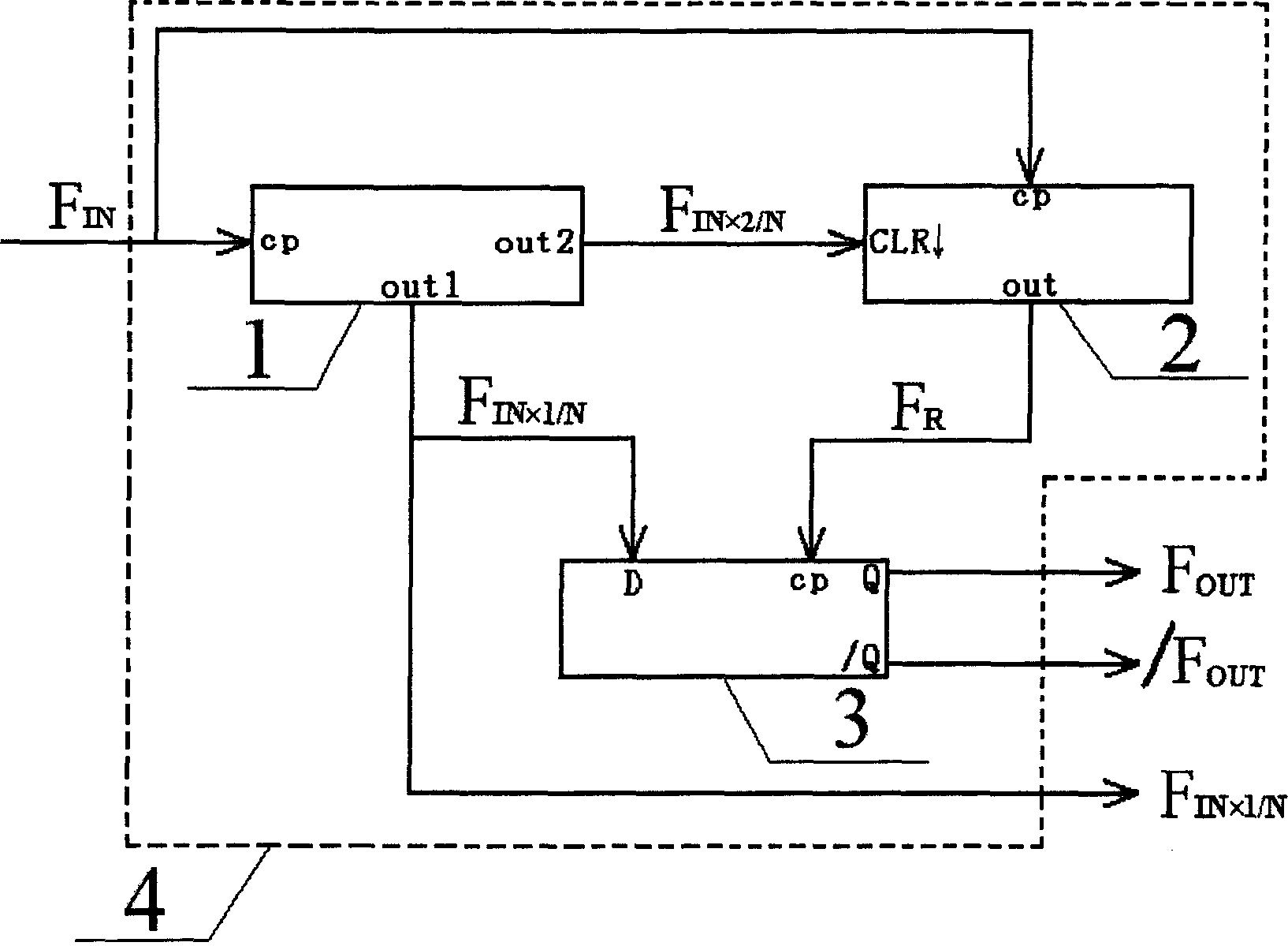
[0029] 1. Part selection

[0030] A. CPLD4 uses EPM1270T144C5 from ALTERA company;

[0031] B, 24-bit counter module 1 is implemented in Verilog HDL language inside CPLD4;

[0032] C. The 23-bit preset counter module 2 is implemented in Verilog HDL language inside CPLD4;

[0033] D, D flip-flop module 3 is realized with Verilog HDL language inside CPLD4.

[0034] 2. Specific implementation methods

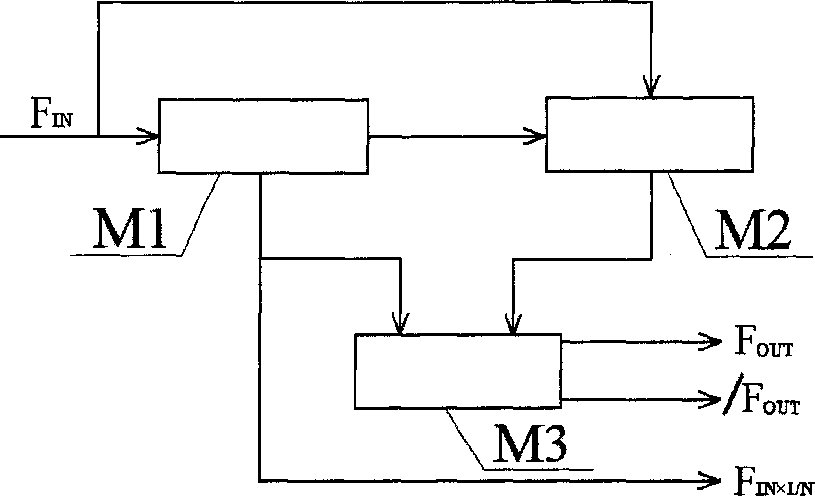
[0035] Depend on figure 1 As shown, the implementation steps of a phase shifting method are as follows:

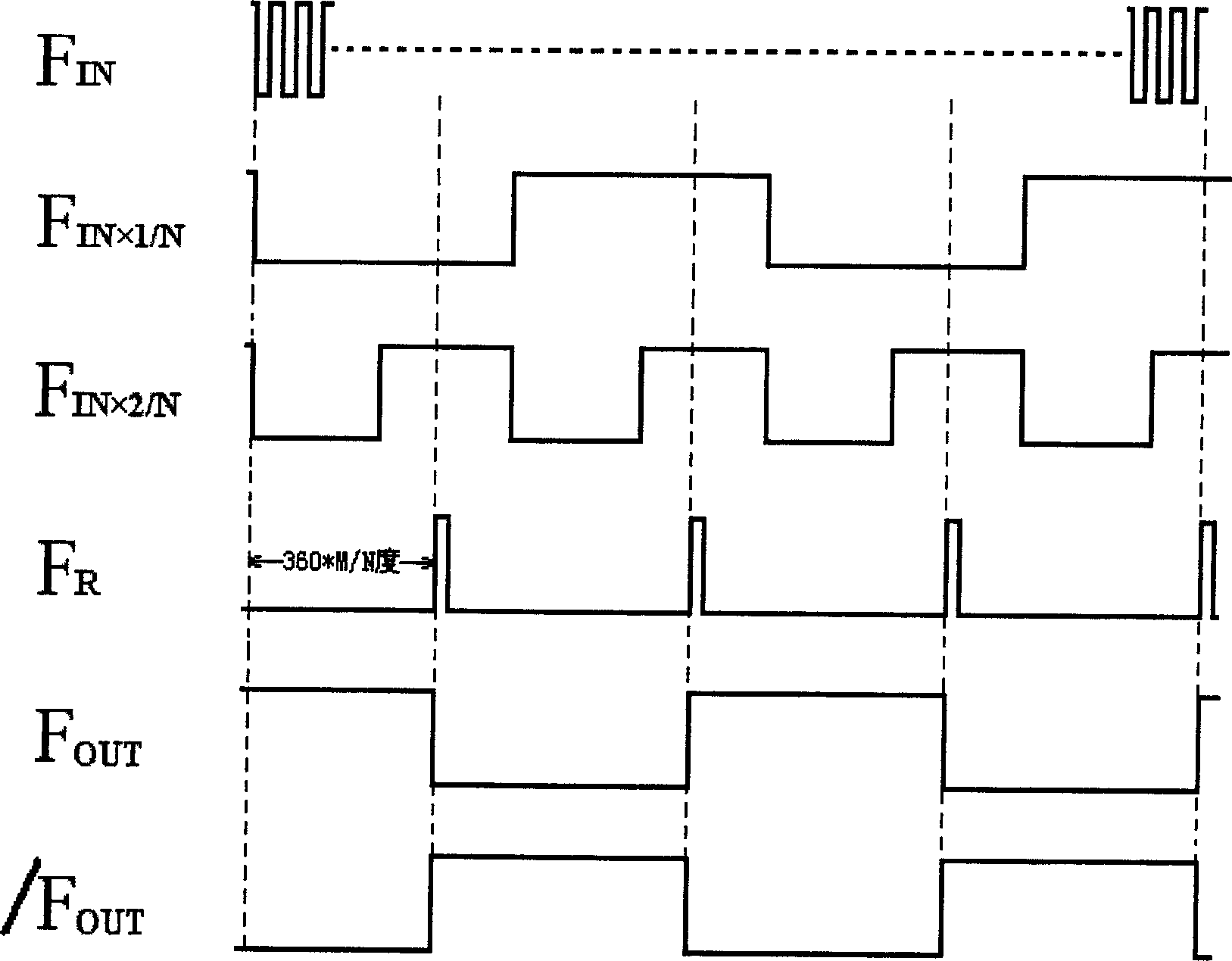
[0036] ①Input signal F IN Connect to the clock input terminal of the n-bit counter M1, and the counter M1 outputs two synchronous square wave signals, one of which is F IN×1 / N , the other signal is F IN×2 / N , F IN×1 / N The frequency is F IN one-nth of N, and F IN×2 / N The frequency is F IN×1 / N Twice of , where N≤2 n And the value of N is determined by the control parameters of the counter M1, F IN×1 / N That is, the square wave signal to be phase-shifted;

[0037] ②In...


PUM


Abstract

This invention discloses a method for precisely shifting phases and a phase-shifter, first of all, which cuts a HF input signal in a counter, which outputs a low frequency square wave signal to be shifted, secondly outputs a two double frequency square wave signal of the being shifted signal, thirdly switches the HF input signal and the two double frequency square wave signal in a preset counter to output a phase-shift square wave labeling square wave and fourthly switches the shift labeling square wave and the low frequency signal to be shifted in a trigger to output the shifted low frequency square wave to finish the phase shift. Device realizing said method include a counter and preset counter and a trigger.

Description

technical field [0001] The invention relates to a digital precision phase shifting method for an atomic clock, and also relates to a phase shifter, which can be widely used in various atomic clocks and precision time equipment. Background technique [0002] In atomic clocks and precision time equipment circuits, there are various methods to achieve phase shifting, but they can be roughly divided into three categories. One is analog phase shifting, which uses amplifiers plus RC phase shifting networks or shift filters. The mechanism is to use the phase-frequency characteristics of the filter network to achieve the purpose of phase shifting, but due to the discrete linear components (such as capacitors, resistors, etc.) It is directly related to power supply fluctuations, so the phase shifting phase value has large fluctuations and it is difficult to make the phase shifting accuracy high; the other is to use the transmission delay time (propagation delay) of the digital gate c...

Claims


Application Information

Patent Timeline
Patent Type & Authority Applications(China)
IPC IPC(8): H03H17/08
Inventor 余钫陈智勇鲁道邦王艳裘晓俊金鑫李超陈云起管妮娜朱熙文盛荣武
Owner WUHAN INST OF PHYSICS & MATHEMATICS CHINESE ACADEMY OF SCI
Why Eureka
Try Eureka