Remote digital kernel phase system
A digital and phase-nuclear technology, applied in electrical components, telephone communications, etc., can solve problems such as inability to support remote phase-nucleation, line power outages, burnt loads, etc., to improve measurement accuracy, eliminate time delays, and ensure reliability.
- Summary
- Abstract
- Description
- Claims
- Application Information
AI Technical Summary
Problems solved by technology
Method used
Image

Examples
Embodiment Construction
[0018] The purpose and effect of the present invention will be more obvious according to the present invention in detail according to accompanying drawing and embodiment.
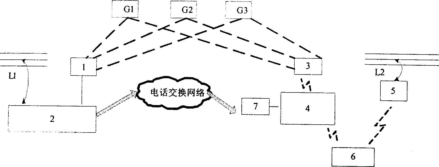
[0019] The remote digital phase verification system consists of two parts: the reference device and the mobile device. The reference device consists of a GPS receiving adapter 1 and a reference host 2. The mobile terminal device is composed of a GPS signal receiving and sending module 3 , a phase detector 4 , a mobile communication host 5 , a handheld testing device 6 and a mobile phone 7 .
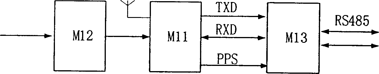
[0020] The GPS receiving adapter 1 is connected to the reference host 2 through the R8485 bus, and is powered by the reference host. The GPS receiving adapter 1 is composed of a GPS-specific receiving module M11, a power adjustment circuit M12, and a communication interface circuit M13. The dedicated GPS receiving module M11 is connected with a dedicated antenna to receive GPS signals. The power regulation circuit M1...
PUM
 Abstract
Description
Claims
Application Information
PatSnap Eureka turns technology decisions into work you can execute. Powered by our Innovation Knowledge Graph, it runs expert workflows across engineering, life sciences, materials and intellectual property. Get your review-ready output in minutes.


