Vehicle air-conditioning related technique having refrigetation cycle of supercritical refrigerant

A vehicle air conditioner and refrigerant technology, which is applied to irreversible cycle compressors, refrigerators, vehicle components, etc., can solve the problems of inability to fully ensure the heat release of refrigerants, difficulty in obtaining heat exchange performance, and poor energy utilization, etc., to achieve Effective use of energy, high cooling performance, and reduced ventilation loss

Inactive Publication Date: 2007-02-14
SHOWA DENKO KK
View PDF0 Cites 6 Cited by
  • Summary
  • Abstract
  • Description
  • Claims
  • Application Information

AI Technical Summary

Problems solved by technology

[0011] Against such a technical background, in the refrigeration cycle of carbon dioxide refrigerant, in the case where only the exhaust gas is introduced into the heat releasing equipment as disclosed in the above-mentioned patent documents, there will be problems such as the temperature of the introduced air and / or the temperature of the refrigerant The disadvantage of variation and / or deviation, which in turn makes it difficult to obtain stable heat exchange performance
Therefore, the heat release of the refrigerant cannot be fully ensured, resulting in an ineffective reduction of ventilation loss, which in turn deteriorates energy utilization

Method used


Image

  • Vehicle air-conditioning related technique having refrigetation cycle of supercritical refrigerant
  • Vehicle air-conditioning related technique having refrigetation cycle of supercritical refrigerant
  • Vehicle air-conditioning related technique having refrigetation cycle of supercritical refrigerant

Examples


Embodiment Construction

[0098] In the following paragraphs, some preferred embodiments of the invention will be described by way of illustration and not limitation. It should be understood that many other modifications to these illustrated embodiments can be made by those skilled in the art in light of this disclosure.

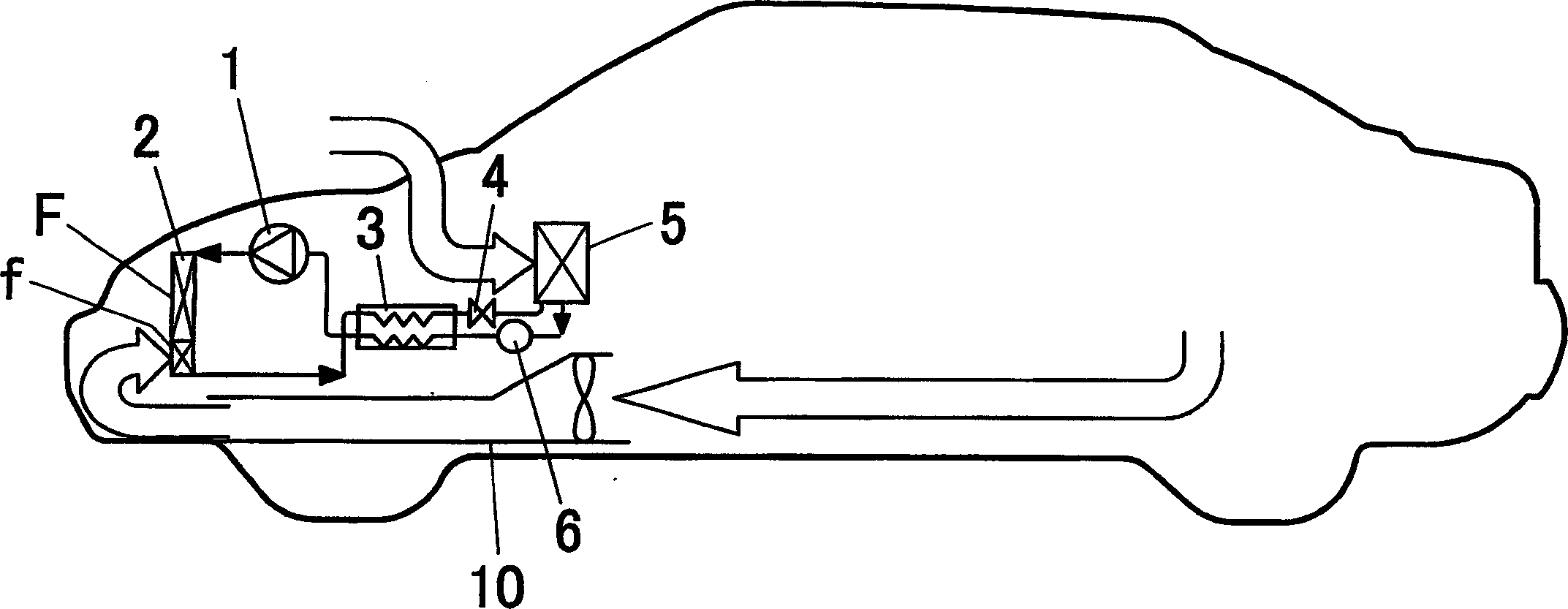
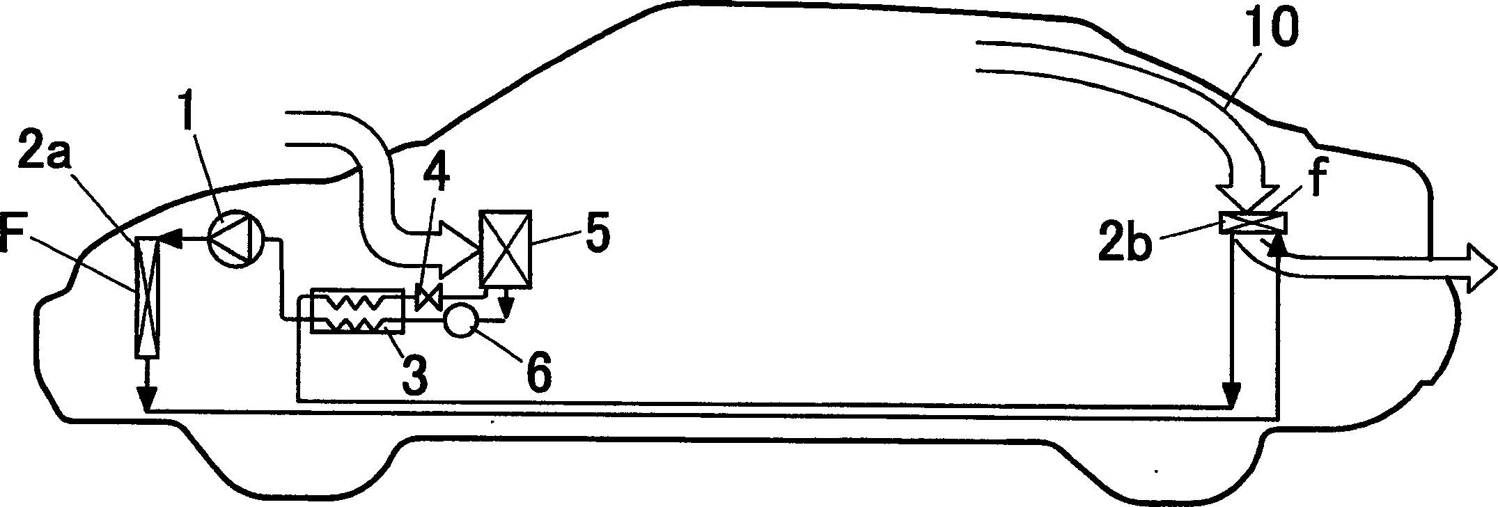
[0099] figure 1 is a schematic configuration diagram showing an automobile air conditioning system using the air conditioning apparatus according to the embodiment of the present invention. The refrigeration cycle used in the car utilizes components such as carbon dioxide (CO 2 ) supercritical refrigerants of refrigerants, and if figure 1 Shown are a compressor 1 , a heat removal device 2 , an intermediate heat exchanger 3 , an expansion valve 4 , an evaporator 5 and an accumulator 6 .

[0100] In this refrigeration cycle, the refrigerant in a supercritical state compressed by the compressor 1 releases heat by exchanging heat with refrigerant cooling air such as ambient air, while...


PUM


Abstract

The invention is directed to a vehicle air-conditioning apparatus in which supercritical refrigerant passing through a refrigerant heat releasing passage P of a heat releasing device 2 exchanges heat with refrigerant cooling air introduced from an air introduction surface F of a heat releasing device 2 to be cooled, and the cooled refrigerant exchanges heat with air to be introduced into a passenger compartment by an evaporator 5. Since at least a part of discharge air discharged from an inside of a passenger compartment is introduced from an air introduction surface F of the heat releasing device 2 as a ventilation loss utilizing air, ventilation loss utilizing air can be used as a part of refrigerant cooling air. It is constituted such that the ventilation loss utilizing air is introduced to the downstream side area f of the refrigerant heat releasing passage P in an air introduction surface F of the heat releasing device 2. Thus, in a vehicle air-conditioning apparatus having a supercritical refrigerant refrigeration cycle, ventilation loss can be reduced while improving refrigeration performance.

Description

[0001] This application claims the benefit of Japanese Patent Application No. 2003-407379, filed December 5, 2003, and U.S. Provisional Application No. 60 / 528,496, filed December 11, 2003, both of which are incorporated herein All for reference. [0002] Cross References to Related Applications [0003] This invention is an application filed under 35 U.S.C. §111(a) and claimed under 35 U.S.C. §119(e)(1) of a U.S. provisional application filed under 35 U.S.C. §111(b) on December 11, 2003 Filing date benefit of No. 60 / 528,496. technical field [0004] The present invention relates to a method with the use of supercritical refrigerants such as CO 2 Vehicle air-conditioning-related technology of a refrigeration cycle of a refrigerant, particularly, relates to, for example, an air-conditioning device for a vehicle, an automobile equipped with the same, a heat releasing device for a vehicle air-conditioning system, and a vehicle air-conditioning method. Background technique [...

Claims


Application Information

Patent Timeline
Patent Type & Authority Applications(China)
IPC IPC(8): B60H1/00F25B1/00F25B27/02B60HB60H1/24B60H1/32F25B9/00
CPCB60H2001/00957B60H2001/00949B60H1/00878F25B2309/061Y02T10/88F25B40/00B60H1/248F25B9/008B60H1/3227B60H1/039
Inventor 新村悦生古川裕一
Owner SHOWA DENKO KK
Why Eureka
Try Eureka