

Tension control equipment
- Summary
- Abstract
- Description
- Claims
- Application Information
AI Technical Summary
Problems solved by technology
Method used
Image

Examples
Embodiment Construction
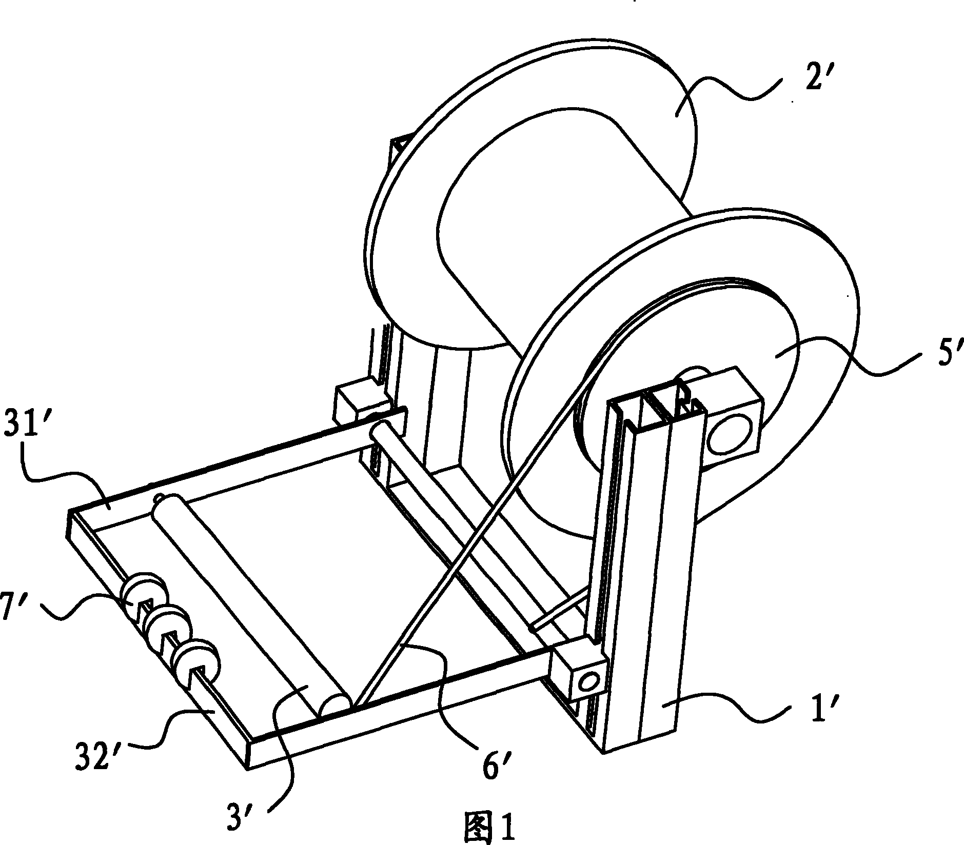
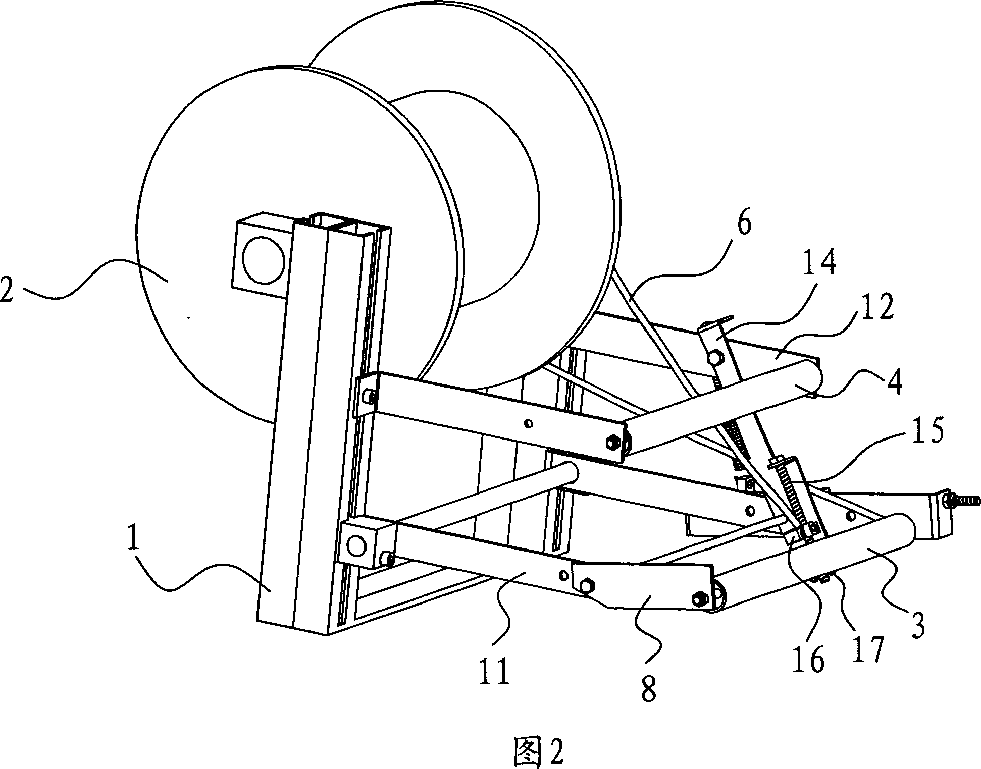
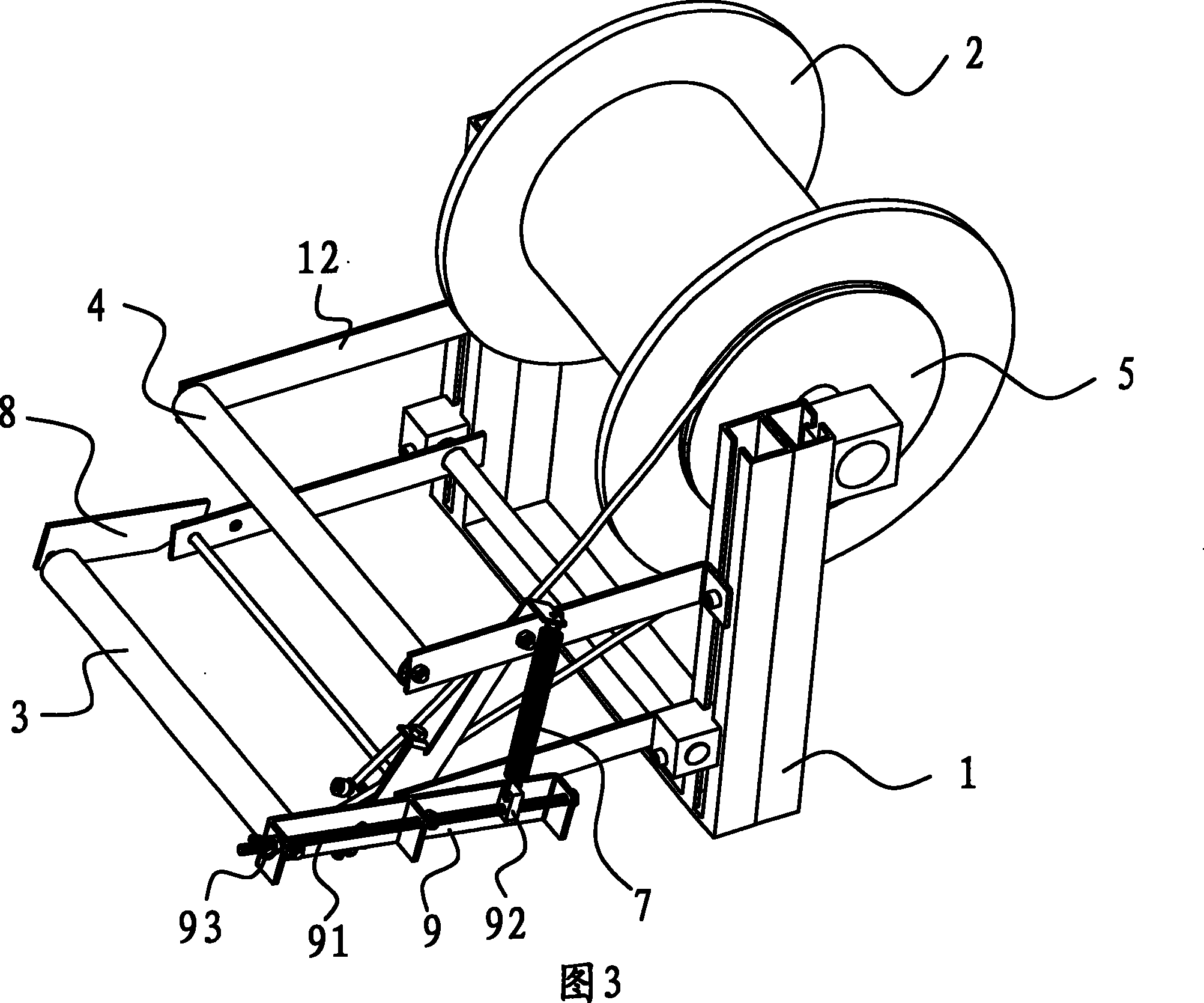
[0015] refer to figure 2 , image 3 , Figure 4 , the embodiment provides a tension control device for elastic uncoiling, which includes a frame 1, a pan head 2, a swing roller 3, a fixed roller 4, a brake wheel 5, a brake band 6, a spring 7, two swing arms 8, a rotating arm9. The cross-section of the pan head 2 is an inverted "I"-shaped structure, and the concave part in the middle is used to wind the rubber band. Applying a pulling force on the end can drive the pan head 2 to rotate against the frictional force of the rolling bearing to complete the uncoiling process of the elastic band. The frame 1 is provided with two support arms 11, the two support arms 11 are perpendicular to the axis of the central axis of the pan head 2 and are respectively located on the frame 1 at the axial ends of the pan head 2. The two swing arms One end of 8 is respectively hinged to the far-end of these two support arms 11, and described swing roller 3 is rotatably arranged on the non-hing...
PUM
 Abstract
Description
Claims
Application Information