Suppressing fluid communication to or from a wellbore

A fluid communication, wellbore technology, applied in the direction of production fluids, wellbore/well components, drilling composition, etc., can solve the problems of complex and expensive completions

Inactive Publication Date: 2007-02-21
SHELL INT RES MAATSCHAPPIJ BV
View PDF4 Cites 17 Cited by
  • Summary
  • Abstract
  • Description
  • Claims
  • Application Information

AI Technical Summary

Problems solved by technology

Applicants have faced this problem in relatively large wellbore casings (7" = 18 cm in diameter) with smaller tubing strings (3.5" = 9 cm in diameter) and in higher wells Completion is complicated at bottom temperature (≥110°C) and high pressure difference between different layers (up to 3000psi=21MPa)
For example cement can set in the tubing or wellbore under the influence of wellbore fluids or local hot zones in the well, and it is very expensive to remove the solidified cement in coiled tubing or production tubing

Method used


Image

  • Suppressing fluid communication to or from a wellbore
  • Suppressing fluid communication to or from a wellbore
  • Suppressing fluid communication to or from a wellbore

Examples


Embodiment Construction

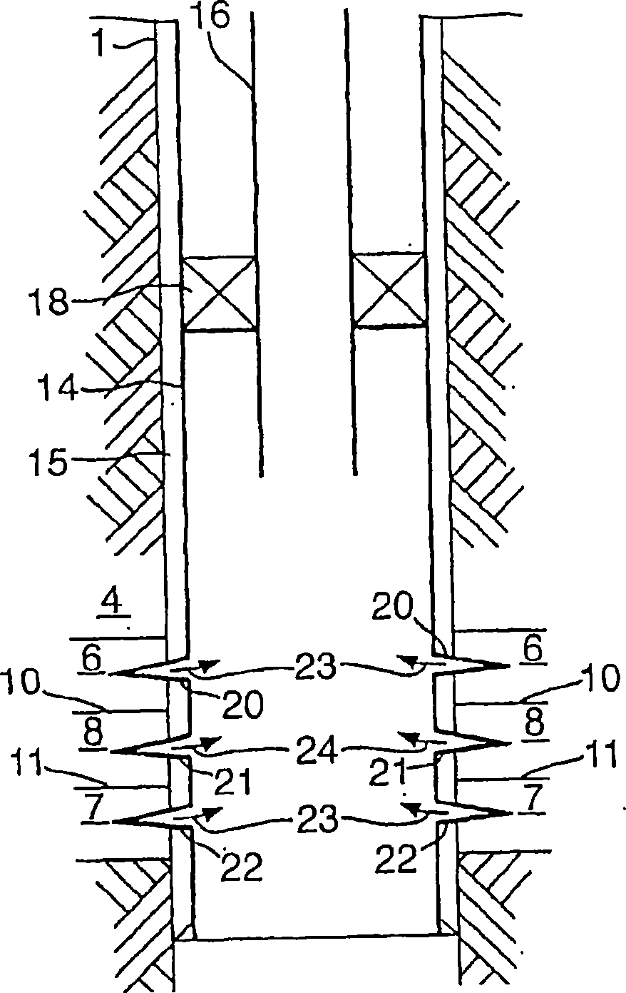
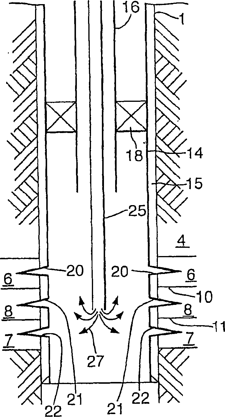
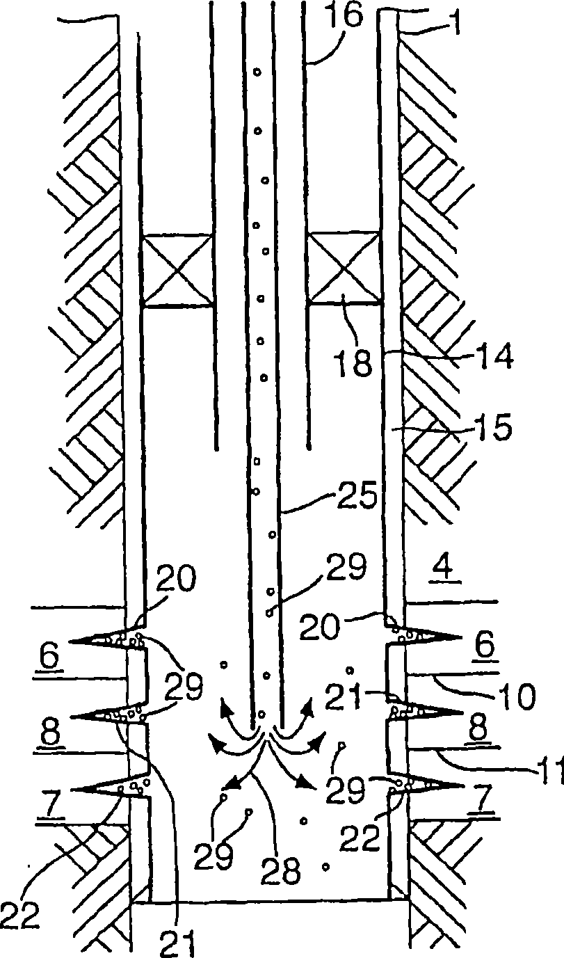
[0038] see figure 1 , figure 1 The lower portion of the wellbore 1 extending from the surface (not shown) into the formation 4 is shown. In this example the strata are stratified. Layers 6 and 7 contain hydrocarbon oil and layer 8 contains water. Layers 6, 7, 8 are separated by boundary or impermeable layers 10, 11 . The wellbore 1 has a casing 14 consisting of a metal casing string, and the annulus 15 between the casing 14 and the wall of the wellbore 1 is filled with cement. The downhole completion is marked by tubing 16 and packers 18 extending to the surface.

[0039] The fluid enters the wellbore 1 from the layers 6, 7, 8 through the perforated holes 20, 21, 22 in the directions indicated by the arrows and is produced to the surface through the tubing 16. This fluid contains oil 23 and a large amount of water 24 which flows from layer 8 . There is a need to seal off the water flowing out of the aquifer 8, in particular through the perforations 21 formed at the int...


PUM


Abstract

A method for suppressing fluid communication to or from a wellbore in a subsurface formation, which method comprises providing a well fluid which comprises solid particles in a carrying fluid, which solid particles include a reactive polymer; introducing the well fluid into the wellbore so that carrier fluid passes through an interface between the wellbore and its surroundings, wherein particles are accumulated at the interface; and allowing the polymer to form a solid plug suppressing fluid communication through the interface; and a well fluid for use in a wellbore, which well fluid comprises solid particles in a carrying fluid, which solid particles include a reactive polymer.

Description

technical field [0001] The present invention relates to a method of inhibiting fluid communication to or from a subterranean formation wellbore, and a wellbore fluid for the wellbore. Background technique [0002] During drilling and operation in subterranean formations, there are many situations where it is desirable to inhibit downhole fluid communication. [0003] For example, fluids produced from hydrocarbon oil or gas wells often contain large amounts of water. The term water here customarily also includes salt water. The source of the water may be formation water intruding from the formation near the hydrocarbon-bearing reservoir or water injected into the formation from the ground. [0004] Water in produced fluids reduces the lift capacity of an oil or gas well and, once produced, can become an environmental problem. Typically, the water content of produced fluids increases with the age of the well, and at some stage the well needs to be treated in order to produc...

Claims


Application Information

Patent Timeline
IPC IPC(8): E21B33/138E21B43/26C09K8/04C09K8/508C09K8/512
CPCC09K8/5086E21B43/26E21B33/138C09K8/512
Inventor J·D·博萨尔特斯G·J·M·范艾登M·J·朗斯
Owner SHELL INT RES MAATSCHAPPIJ BV
Why Eureka
Try Eureka