
Disc reproduction device and method

A device and audio data technology, applied in magneto-optical discs, read-only discs, disc-shaped record carriers, etc., can solve the problems of complex disc playback equipment and time-consuming jump operations

Inactive Publication Date: 2007-02-21
PANASONIC CORP
View PDF1 Cites 0 Cited by
  • Summary
  • Abstract
  • Description
  • Claims
  • Application Information

AI Technical Summary

Problems solved by technology

[0010] However, the above-mentioned optical disc playback device with the conventional structure has such a problem that a jump operation of the optical pickup to the target position is required every time a request for searching the head of a specific track is issued; and, when the current position and the target position are separated, , the skip operation is time consuming, thereby generally causing a delay from issuing a head seek request until outputting the audio data for such a head seek
[0012] However, the track head search according to JP-A-2002-100123 also involves a problem: although the audio data used for head search in a plurality of channels is stored in the memory, when a head search for a specific track is issued, audio data different from that used in the head search for a specific track is erased when requesting a head search
Therefore, the disc playback apparatus is complicated in terms of arranging the switching means; and in fact, difficulty has been encountered in performing switching of sound playback while maintaining high audio quality.
[0014] Furthermore, since each of the techniques described in JP-A-2002-100123 and JP-A-7-176174 is limited to the head search of the audio track, audio data at an arbitrary position, such as an AB repeating pattern, is to be output therein. Difficulties have been encountered using the above method in cases such as

Method used


Image

  • Disc reproduction device and method
  • Disc reproduction device and method
  • Disc reproduction device and method

Examples


no. 1 approach

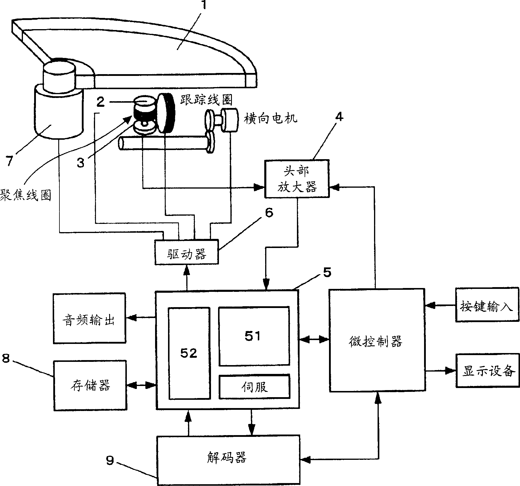
[0059] Next, an optical disc playback device according to a first embodiment of the present invention will be described with reference to the accompanying drawings. first, Figure 5 A map within memory 8 is shown. The memory 8 having a ring buffer structure is divided into: an area called a work area for storing audio data having a specific length and belonging to a plurality of tracks; The remaining audio data of one track following the audio data having a certain length is stored and output.

[0060] In the processing belonging to the track head search, the basic requirement is to divide the work area into some tracks recorded in the optical disc 1, and to store the audio data sequentially from the head of the music selection to the tracks in the work area. The head position of the corresponding segmented region of the track (WP n ). The basic requirement for the amount of audio data to be stored in each divided area of ​​the audio track is greater than the amount of dat...

no. 2 approach

[0073] Next, an optical disc playback device according to a second embodiment of the present invention will be described with reference to the accompanying drawings.

[0074] The AB repeat process between two points on the track is described by referring to FIGS. 12 and 13 .

[0075] First, when point A is set, the read pointer is moved to the head position (WP) of the work area (step S1211). To set the work range of the read pointer to (work area+track buffer), the ring buffer MAX is set to the end (WPe) of the work area (step S1212). In the write process, the target position to which the optical pickup 3 is to be moved by the jump operation is set as the position of point A on the disc, while the write pointer is set to the same position as the read position (step S1213).

[0076] Subsequently, write processing is performed (step S1214), such as Figure 7 shown in . When a predetermined amount of data is stored in the memory 8, output of the audio data written in the memo...

no. 3 approach

[0084] Next, an optical disc playback device according to a third embodiment of the present invention will be described with reference to the accompanying drawings.

[0085] When a request to set point A is issued during playback of audio data, the audio data stored in the track buffer is transferred to the work area by DMA (Direct Memory Access) transfer. In this case, as Figure 14 As shown in , the write MAX is set to the current read position so that the audio data to be newly written in the track buffer does not overwrite the audio data stored in the write buffer (S1401). Subsequently, the current read position is set as a DMA transfer start position (S1402). DMA transfer is started (S1403). When the transfer of audio data has reached the end of the work area, the transfer is terminated (S1404). Figure 15 The state of the read and write pointers during this process is shown.


PUM


Abstract

There are provided a disc reproduction device and a reproduction method capable of promptly reproducing a sound at an arbitrary position on the disc when the reproduction is requested, without providing complicated switching means. The disc reproduction device includes access means for accessing a disc and access control means for controlling the access means to an arbitrary position on the disc. The disc reproduction device further includes: storage means divided into a first area for storing at least one audio data of a particular length of at least one track and a second area for storing remaining audio data of the one track; write-in means for accessing the disc, writing the audio data of the particular length starting at an arbitrary position of the one track in the first area, and writing the remaining audio data in the second area during reproduction of the audio data of the particular length; and read-out means for continuously reading out the audio data of the particular length and the remaining audio data.

Description

technical field [0001] The present invention relates to a disc playback device and a method for playing back a disc. Background technique [0002] Next, a technique for playing back audio data recorded in a conventional optical disc will be described. figure 1 A structural block diagram of a conventional optical disc playback device is shown. [0003] exist figure 1 In this case, the laser beam irradiated on the optical disc 1 is reflected by the optical disc 1 and reaches an optical pickup 3 via a lens 2 . The laser beam that has arrived is converted into an electrical signal by the optical pickup 3; and the converted electrical signal is amplified by a head amplifier 4 to be synthesized into a focus error signal and a tracking error signal. [0004] The focus error signal and the tracking error signal are input to the servo and signal processing LSI 5 . The servo and signal processing LSI 5 performs focus servo processing according to the focus error signal. The contr...

Claims


Application Information

Patent Timeline
Patent Type & Authority Applications(China)
IPC IPC(8): G11B20/10G11B20/12G11B27/10
CPCG11B2220/2545G11B2220/213G11B20/10G11B2220/2529G11B2020/10546G11B2220/2562G11B27/105G11B2020/10768
Inventor 岸本浩司
Owner PANASONIC CORP
Learn More