
Preferential ground and via exit structures for printed circuit boards

A technology for exporting structures and circuit boards, used in printed circuits, printed circuits, printed circuit manufacturing, etc.

Inactive Publication Date: 2007-02-21
MOLEX INC
View PDF1 Cites 29 Cited by
  • Summary
  • Abstract
  • Description
  • Claims
  • Application Information

AI Technical Summary

Problems solved by technology

It is important to control the impedance of these transmission lines to minimize crosstalk and electrical interference during device operation without unduly complicating the board design and layout of the circuits on that board

Method used


Image

  • Preferential ground and via exit structures for printed circuit boards
  • Preferential ground and via exit structures for printed circuit boards
  • Preferential ground and via exit structures for printed circuit boards

Examples


Embodiment Construction

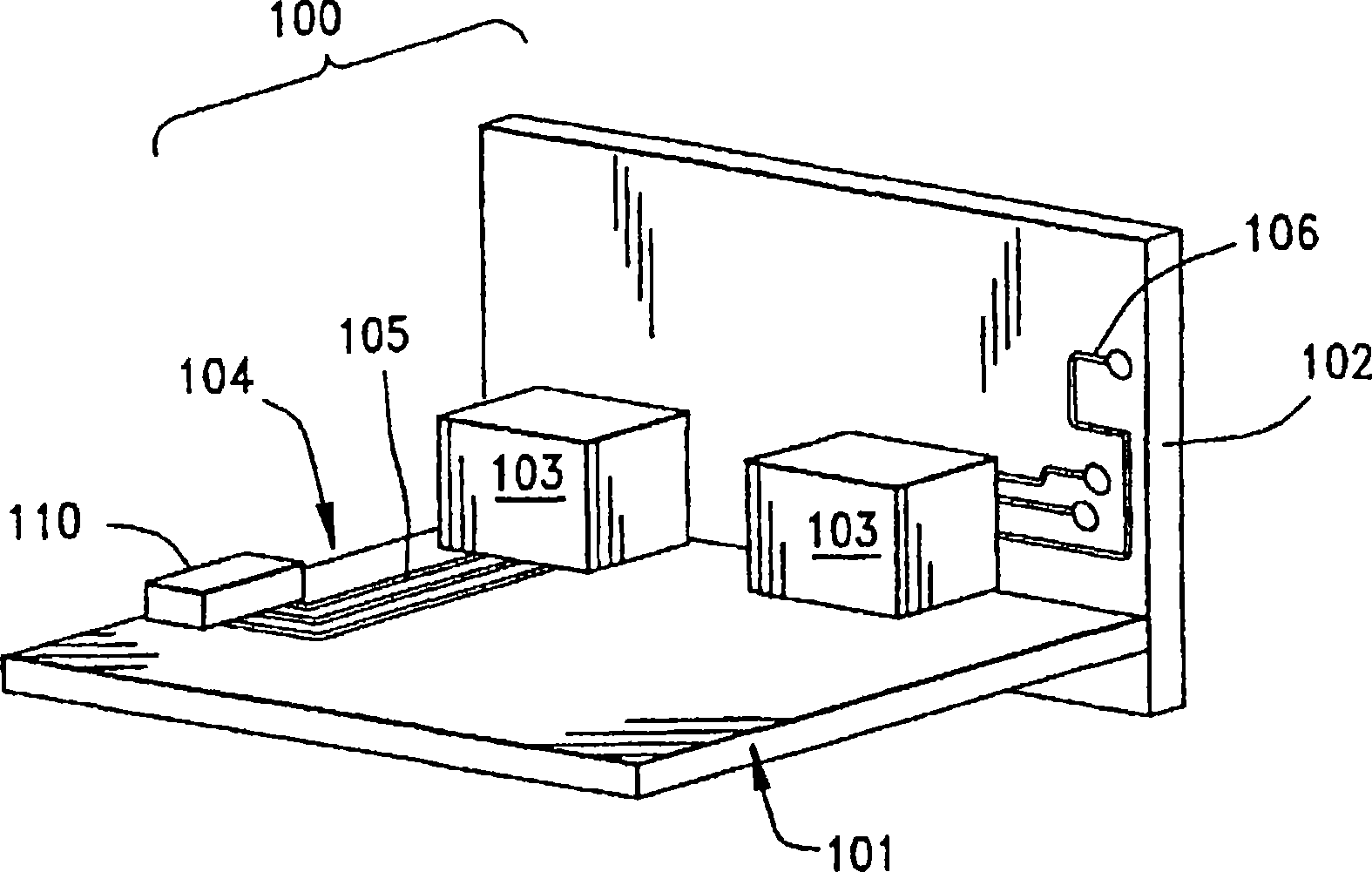
[0057] figure 1 It is a perspective view of the backplane assembly 100. In the backplane assembly 100, a printed circuit board (herein referred to as “main board”) 101 is connected to an auxiliary circuit board 102 through one or more connectors 103. The connector 103 known in the prior art connects the conductive circuit 104 to a similar circuit 106 arranged on the auxiliary circuit board 02, wherein the conductive circuit 104 utilizes conductive traces 105 arranged on the surface of the main board 101. These circuits 104, 106 generally lead to an electronic device 110 mounted on a circuit board.

[0058] The cable can be used to figure 1 The component 100 is connected to another electronic component, and these cables are just a form of electronic signal transmission line. Other forms of such transmission lines may be incorporated into the circuit boards 104, 106 of the assembly, and one such form may take a plurality of conductive traces arranged on the circuit board (or laye...


PUM


Abstract

A circuit board design is disclosed that is useful in high-speed differential signal applications uses either a via arrangement or a circuit trace exit structure. A pair of differential signal vias in a circuit board are surrounded by an opening that is formed within a ground plane disposed on another layer of the circuit board. The vias are connected to traces on the circuit board by way of an exit structure that includes two flag portions and associated angled portions that connect the flag portions to circuit board traces. In an alternate embodiment, the circuit board traces that leave the differential signal vias are disposed in one layer of the circuit board above a wide ground strip disposed on another layer of the circuit board in a triangular pattern when viewed in section.

Description

Technical field [0001] The present invention generally relates to circuit board configurations, and more particularly, the present invention relates to via configurations applied on printed circuit boards for high-speed electrical transmission applications. Background technique [0002] In the field of data communication, the data transmission speed has been steadily increased in the past few years. The increase in speed requires the development of high-speed electronic devices for use in the telecommunications field (for example, Internet applications) as well as in data transmission and storage applications. In order to increase the transmission speed of electrical signals, it is known to use differential signals. [0003] Twisted pair cables are usually used to send differential signals, and are usually used mainly in cables. These signal cables have one or more twisted pairs that are twisted together along the length of the cable, and each such twisted pair is surrounded by a...

Claims


Application Information

Patent Timeline
Patent Type & Authority Applications(China)
IPC IPC(8): H05K1/02H01L23/64H01L23/66H01R12/16H01R12/51H01R13/658H05K1/11H05K3/42
CPCH01L2924/1903H05K1/0245H05K2201/09636H05K2201/044H05K1/115H05K2201/09236H05K3/429H05K2201/09609H05K2201/10189H01L2223/6627H05K1/0222H05K1/0251H05K2201/09718H01L2924/0002H01L2924/00H05K1/09
Inventor 肯特·E·雷尼尔大卫·L·布伦克尔梅尔廷·U·奥布奥基里
Owner MOLEX INC
Learn More