

Sleeve for hydrodynamic bearing device, hydrodynamic bearing device and spindle motor using the same, and method for manufacturing sleeve
A technology of fluid bearings and bushings, which is applied to bearing components, shafts and bearings, mechanical equipment, etc., and can solve problems such as damage to reliability of dynamic pressure fluid bearing devices
- Summary
- Abstract
- Description
- Claims
- Application Information
AI Technical Summary
Problems solved by technology
Method used
Image

Examples
no. 1 approach
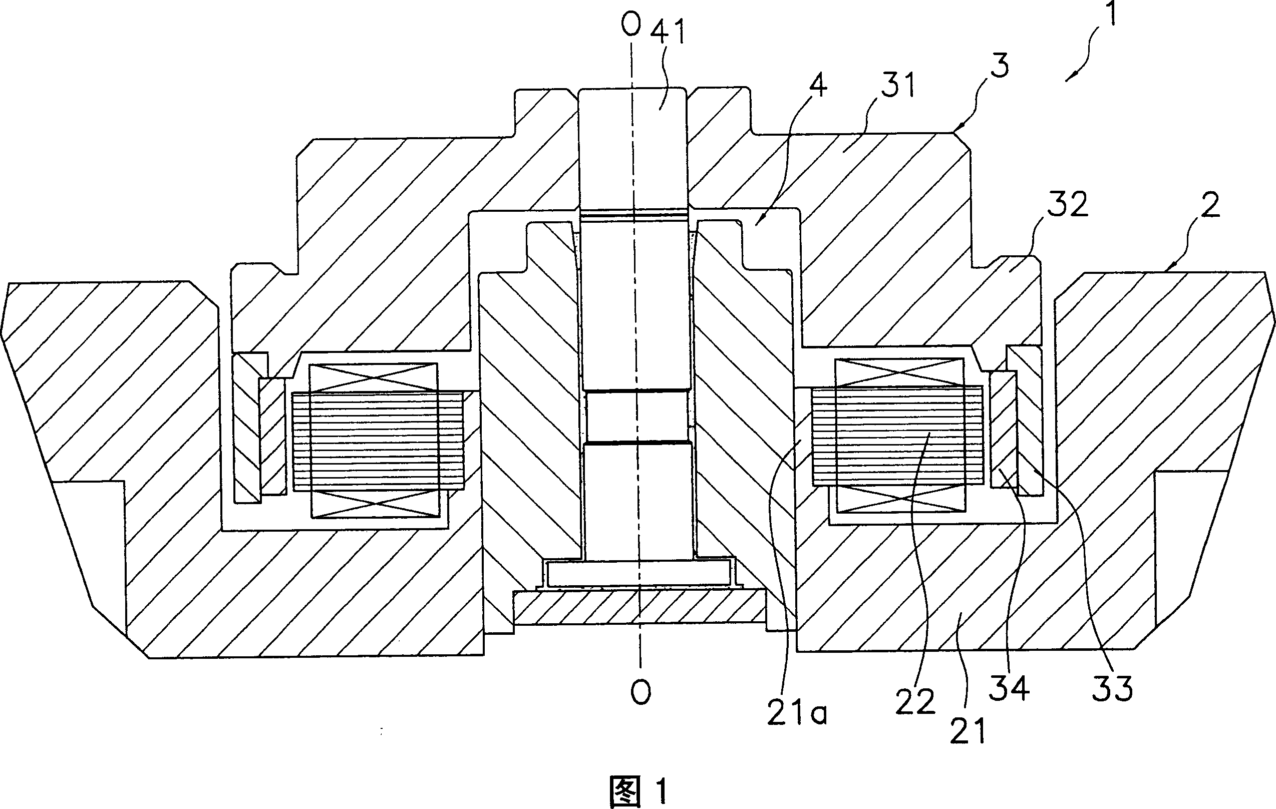
[0122] FIG. 1 shows a schematic longitudinal cross-sectional view of a spindle motor 1 including a fluid bearing device using a boss as a first embodiment of the present invention. O-O as shown in FIG. 1 is the rotation axis of the spindle motor 1 . In addition, in the description of this embodiment, for the sake of convenience, the vertical direction in the drawings is expressed as "axially upper side", "axially lower side", etc., but the actual mounting form of the spindle motor 1 is not limited.
[0123] The spindle motor 1 mainly includes: a base plate 2 (stationary part), a rotor 3 (rotating part), and a fluid bearing device 4 . Hereinafter, details of each component will be described.
[0124] The bottom plate 2, constituting the portion of the spindle motor 1 on the stationary side, is fixed to or formed on, for example, a housing (not shown) of the recording disk unit. The base plate 2 has a socket portion 21 and a stator 22 is attached thereto. The socket portion 2...
no. 2 approach
[0155] In addition, in the first embodiment, shot blasting and resin impregnation are used together to manufacture a bush with a high sealing effect, but other sealing treatments and manufacturing methods are also conceivable. Next, the sealing process of the boss|hub which is 2nd Embodiment of this invention, and its manufacturing method are demonstrated. In addition, this embodiment relates to the case where iron-based sintering is mainly used.
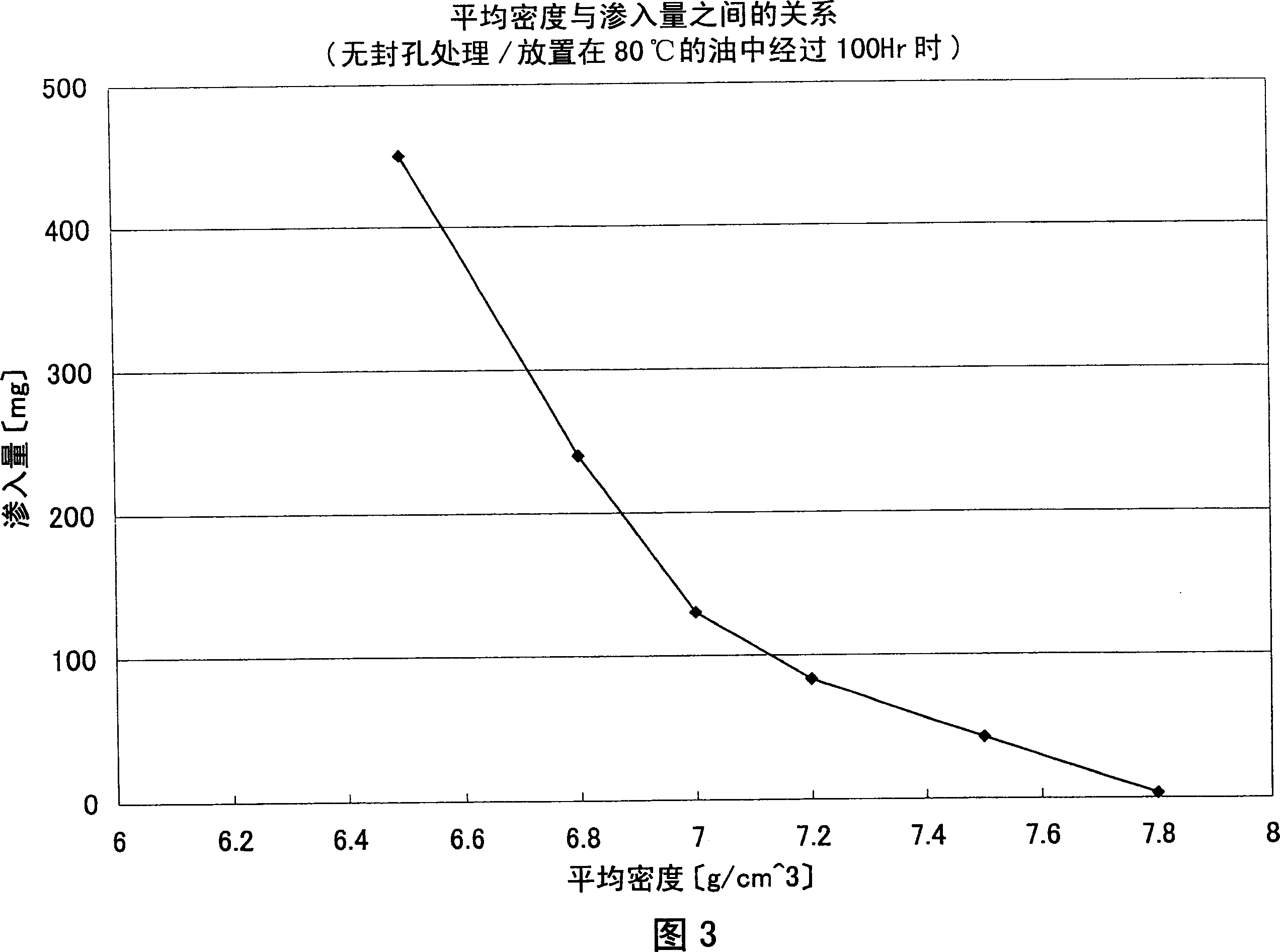
[0156] In addition to the shot peening and resin impregnation treatments described above, it is conceivable to perform hole sealing treatment by high-temperature oxidation of the surface of the sintered metal that is brought into contact with high-temperature steam. Fig. 10 shows the relationship between the average density and the penetration amount of lubricating oil when steam treatment is performed. FIG. 10 shows the case where the thickness of the film formed by steam treatment is 2 (μm). Comparing FIG. 3 and FIG. 10 , it can...
no. 3 approach
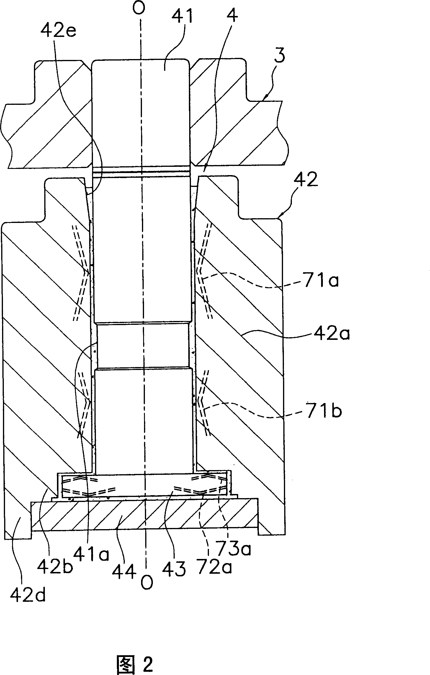
[0172] In the bushings of the first and second embodiments described above, it is possible to prevent the support pressure of the bearing portion from being released through the air holes. However, when the shaft has a thrust flange, the shape of the end portion of the sleeve becomes complicated as shown in FIG. 2 . Specifically, the joint portion between the hub main body and the cylindrical protrusion has an intricate shape, and the shape of the molding die also becomes complicated. As a result, in the filling process, it is difficult to fill the metal powder into this part, and the density of the metal powder cannot be increased. Therefore, the manufacturing method of the boss|hub which is 3rd Embodiment of this invention is demonstrated based on the manufacturing method of 1st Embodiment.
[0173] This manufacturing method is characterized by a setting treatment step. Fig. 15 is a schematic diagram showing a setting process in a manufacturing method according to a third ...
PUM
| Property | Measurement | Unit |
|---|---|---|
| Density | aaaaa | aaaaa |
| Thickness | aaaaa | aaaaa |
| Density | aaaaa | aaaaa |
Abstract
Description
Claims
Application Information