

Method and equipment for measuring fluid viscosity of capillary pipeline
A measuring device and capillary technology, which are applied in the field of fluid viscosity measurement and device for capillary pipelines, can solve the problems of difficulty in heating and temperature control of a sample needle, inability to realize rapid online detection of fluid viscosity, and inability to realize online measurement in Newtonian fluid viscosity measurement. , to achieve the effect of obtaining test results immediately, saving liquid for testing, and accurate and reliable data
- Summary
- Abstract
- Description
- Claims
- Application Information
AI Technical Summary
Problems solved by technology
Method used
Image

Examples
Embodiment 1
[0026] A method for measuring the fluid viscosity of a capillary pipeline, which uses a fluid viscosity measuring device for adding a sample capillary pipeline to collect data, uses a solution processor to process the collected data, and outputs the viscosity data of the measured fluid;
[0027] a. Inject the reference liquid into the reference liquid sample cup, put the measured liquid into the measured liquid sample cup, make the fluid viscosity measuring device in the environment of 20 ° C ~ 40 ° C, and make all the sample cups The temperature of the liquid should be uniform; a simple measure is to place the sample cup in the environment for 20 to 40 minutes after injecting the liquid; or use a ventilation device to generate a circulating air flow to make the liquid temperature in all the sample cups uniform;
[0028] b. Start the fluid viscosity measuring device, insert the sampling needle into the reference liquid in the reference liquid sample cup, use the sampling needle...
Embodiment 2
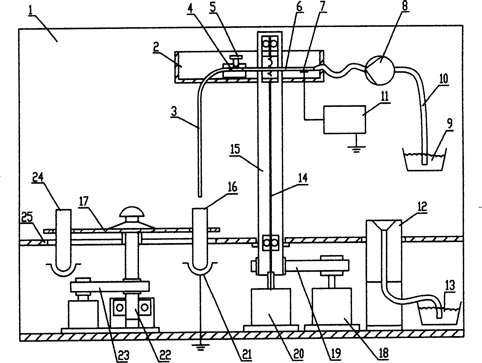
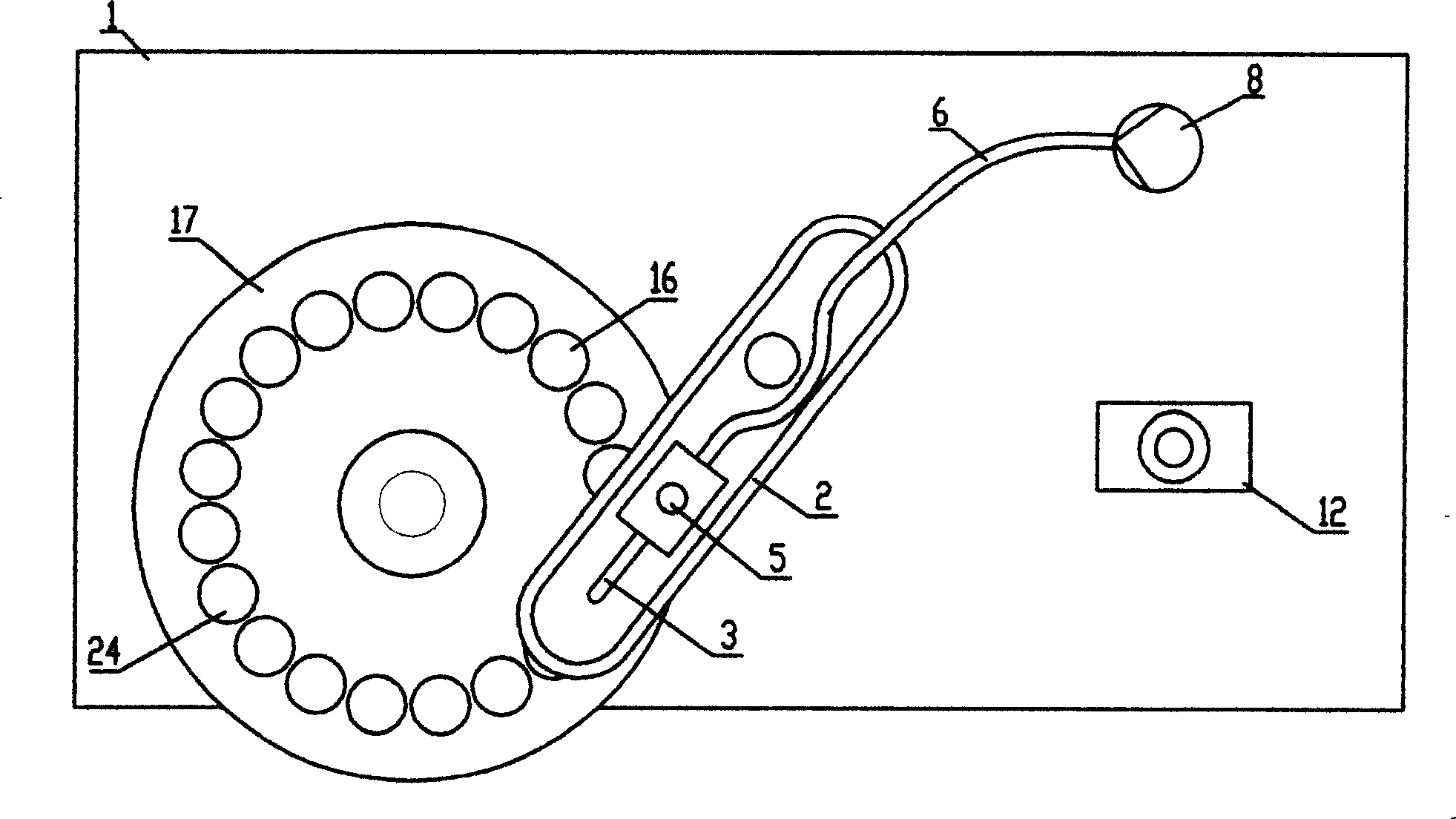
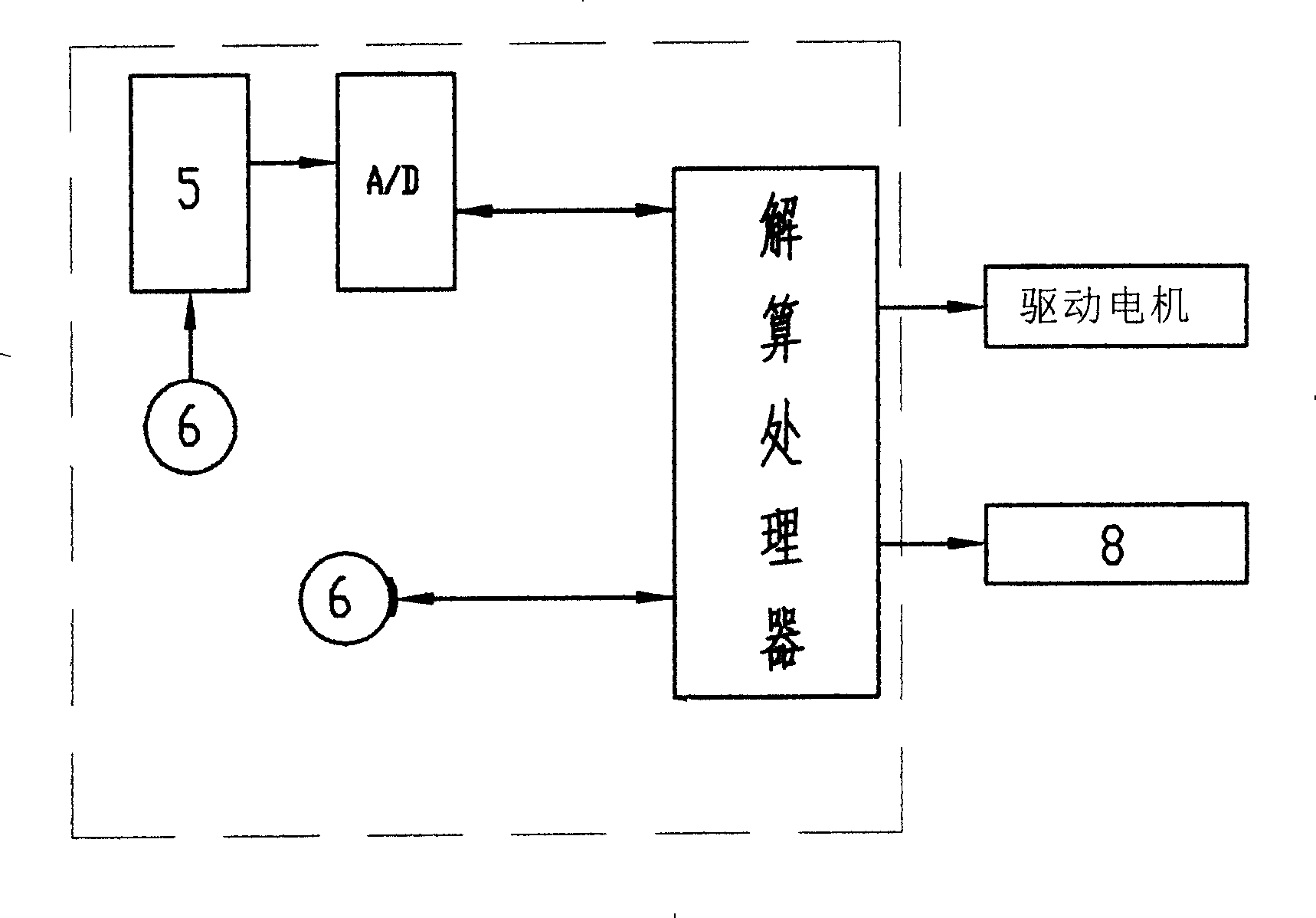
[0046] see figure 1 , figure 2 , image 3 , the fluid viscosity measuring device of the present invention has a frame 1, the frame is made of engineering plastics, the frame is provided with a sample needle mounting frame 2, and the mounting frame can adopt a conventional swing arm lifting type mounting frame , a vertical capillary sampling needle 3 is fixed on the mounting frame of the sampling needle, and the sampling needle communicates with a sampling pump 8 through a sampling pipeline 6, thereby forming a sampling capillary pipeline. A pressure sensor 5 is arranged on the sampling needle body or the sampling pipeline, and the pressure sensor is electrically connected to a solving processor through a data line, and the solving processor is connected to the sampling pump through a control line. The input end is electrically connected, and a sample cup holder 17 is arranged under the capillary-type sampling needle, and a reference liquid sample cup 24 and a measured liqui...
Embodiment 3
[0054] In an embodiment of the present invention, the sample cup holder is a linearly transposed sample tray, and the mounting frame for the sampling needle is a linearly movable mounting frame. The linear transposition sample disk reciprocates along the Y axis, and the sample needle installation frame reciprocates along the X axis, and can be raised and lowered. The sample disk is provided with a reference liquid sample cup and a measured liquid sample cup.
[0055] Figure 4 , Figure 5 The specific structure of the embodiment is shown. There is a frame 201, on which a sample needle mounting frame 212 is arranged. Make up and down movement along Z guiding column 215. The drive motor, transmission screw, and Z guide column are installed on a Z seat plate 227, and the Z seat plate is installed on the X seat plate 213 through the X guide rail 203, the belt transmission mechanism 202, and the drive motor 216, and can be moved along the X direction. The guide rail 203 moves le...
PUM
 Abstract
Description
Claims
Application Information