Vapor deposition source with minimized condensation effects
A technology of deposition source and steam, applied in the direction of vacuum evaporation plating, coating, electric solid devices, etc., can solve the problems of uneven deposition, uneven deposition, leakage, etc., achieve the effect of improving internal condensation and reducing material condensation
- Summary
- Abstract
- Description
- Claims
- Application Information
AI Technical Summary
Problems solved by technology
Method used
Image

Examples
Embodiment 1
[0054] Example 1: No End Heater
[0055] A 50 cm long container made of stainless steel sheet material was covered with a split plate / heater assembly. Use Grafoil TM The gasket seals between the lid and the container and is used by Cogemica TM The resulting gasket prevents shorting of the electrical circuit between the lid and the container. The spacer, cover and clamping means are surrounded by holes around the perimeter through which the container is bolted and tightened to secure the cover to the container.
[0056] The open plate has 49 openings, on the central 32 cm of the plate, the center spacing of the openings is 1 cm. The spacing at the ends varies as follows. The respective center positions of openings 1-9 are 0, 6, 12, 19, 26, 34, 42, 51 and 60 mm. The respective center positions of openings 40-49 are 380, 389, 398, 406, 414, 421, 428, 434 and 440 mm. Such an opening spacing pattern is chosen to compensate for the size effect of the finite source which causes...
Embodiment 2
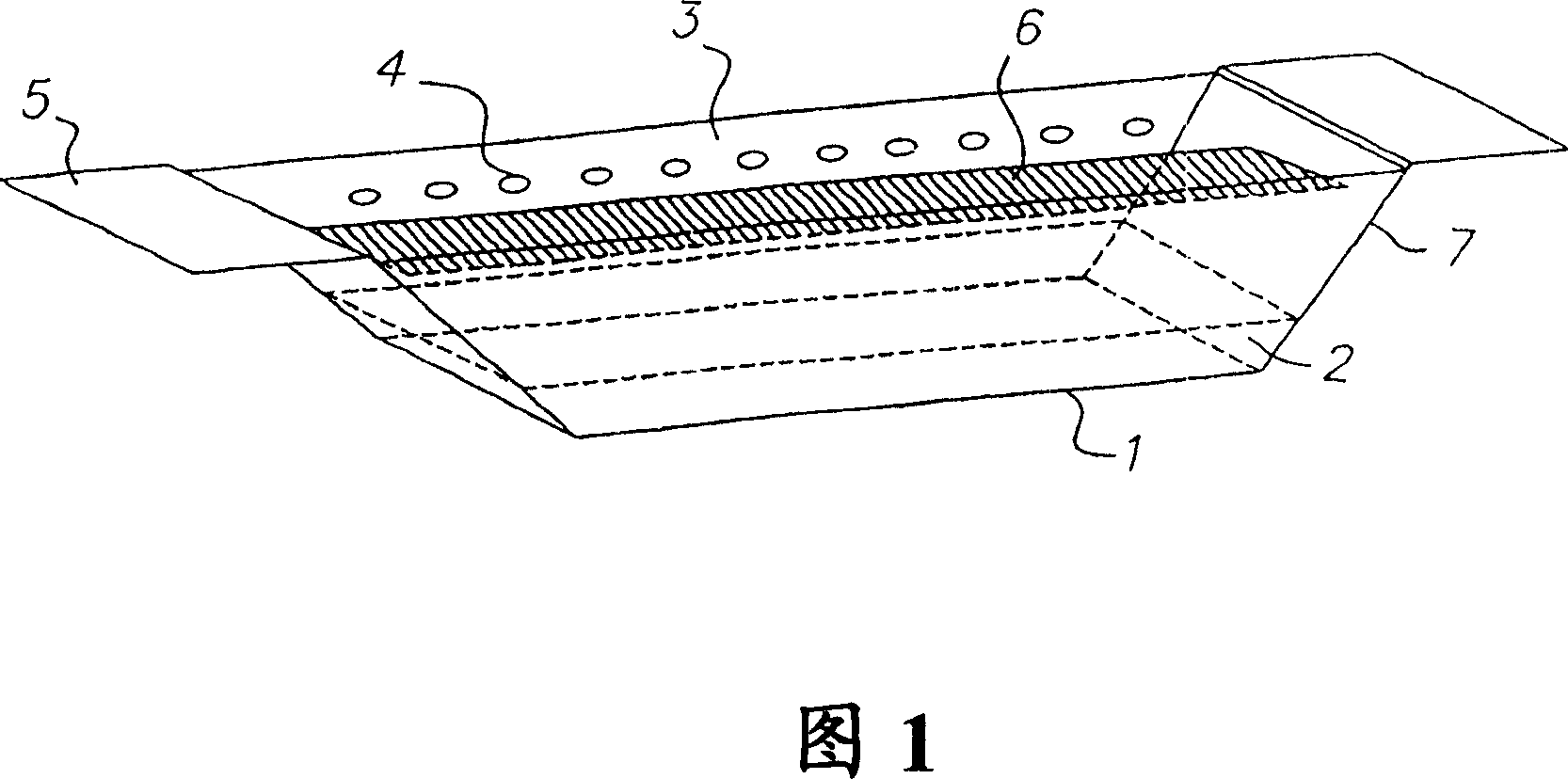
[0067] The same experimental setup as in Example 1 above was used, with the addition of heating the ends of the vessel to reduce condensation of material on the vessel. The rectangular container in Example 1 was replaced by a container with sloped end walls, such as the container shown schematically in FIG. 1 . The angle of inclination of the end walls to the horizontal is about 35 degrees. The source was filled with 200 g of Alq and installed in a vacuum chamber below the sensor array described in Example 1. The conductance ratio and operating pressure at a given rate are as described in Example 1.
[0068] A heating current is applied along the apertured plate, and the output of the source is ramped up to produce a detectable deposition rate on the sensor array. The heating current was used to control the rate, and the average rate increased from zero to about 50A / s within 8 hours, then decreased to between 4-8A / s, and maintained for 14 hours. The rate was then increased ...
Embodiment 3
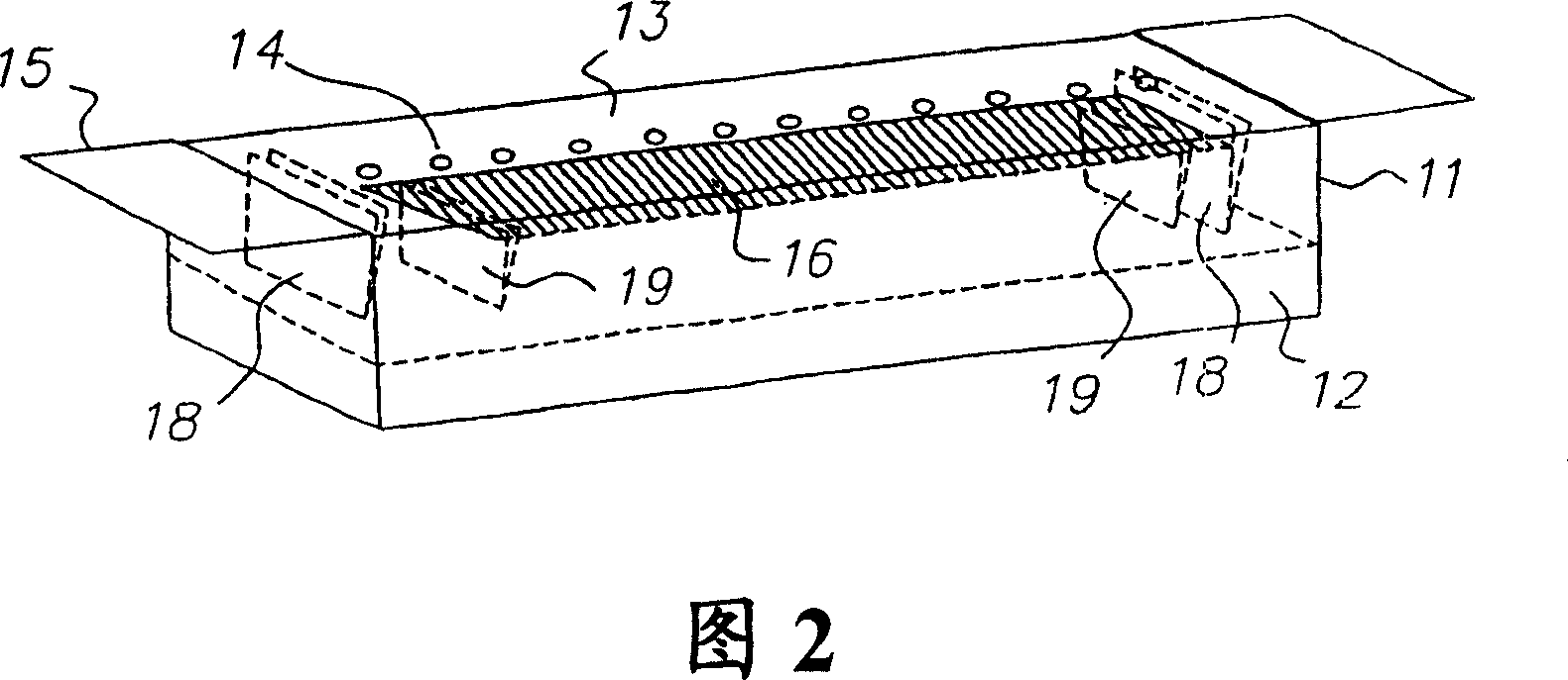
[0072] The same experimental setup as in Example 1 above was used, with the addition of a structure to heat the sides of the vessel to reduce condensation of material on the vessel. A metal sheet (extension 18 in Figure 2) is spot welded to each end of the opening plate (cover 13 in Figure 2). The source was filled with 200 g of Alq and installed in a vacuum chamber below the sensor array described in Example 1. The conductance ratio and operating pressure at a given rate are as described in Example 1.
[0073] A heating current is applied along the apertured plate, and the output of the source is ramped up to produce a detectable deposition rate on the sensor array. The heating current was used to control the rate, and the average rate increased from zero to about 50A / s within 8 hours, then decreased to between 4-8A / s, and maintained for 14 hours. The rate was then increased again to about 50 A / s in 1 / 2 hour and held at this rate for 12 hours. The rate was then reduced to ...
PUM
 Abstract
Description
Claims
Application Information
 - R&D
- Intellectual Property
- Life Sciences
- Materials
- Tech Scout
- Unparalleled Data Quality
- Higher Quality Content
- 60% Fewer Hallucinations
Browse by: Latest US Patents, China's latest patents, Technical Efficacy Thesaurus, Application Domain, Technology Topic, Popular Technical Reports.
© 2025 PatSnap. All rights reserved.Legal|Privacy policy|Modern Slavery Act Transparency Statement|Sitemap|About US| Contact US: help@patsnap.com