

Directional diagram reconstructable aerial having double folding slot structure and its array
A technology of reconstructing antennas and double folding is applied in the field of electronics, which can solve the problems of undetermined technical solutions, and achieve the effects of light weight, increased control freedom, and low cost.
- Summary
- Abstract
- Description
- Claims
- Application Information
AI Technical Summary
Problems solved by technology
Method used
Image

Examples
Embodiment Construction
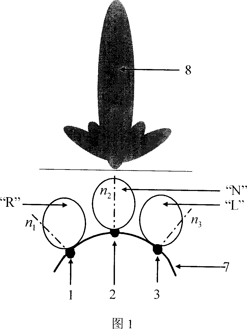
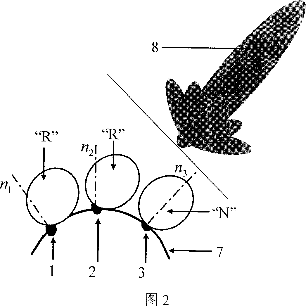
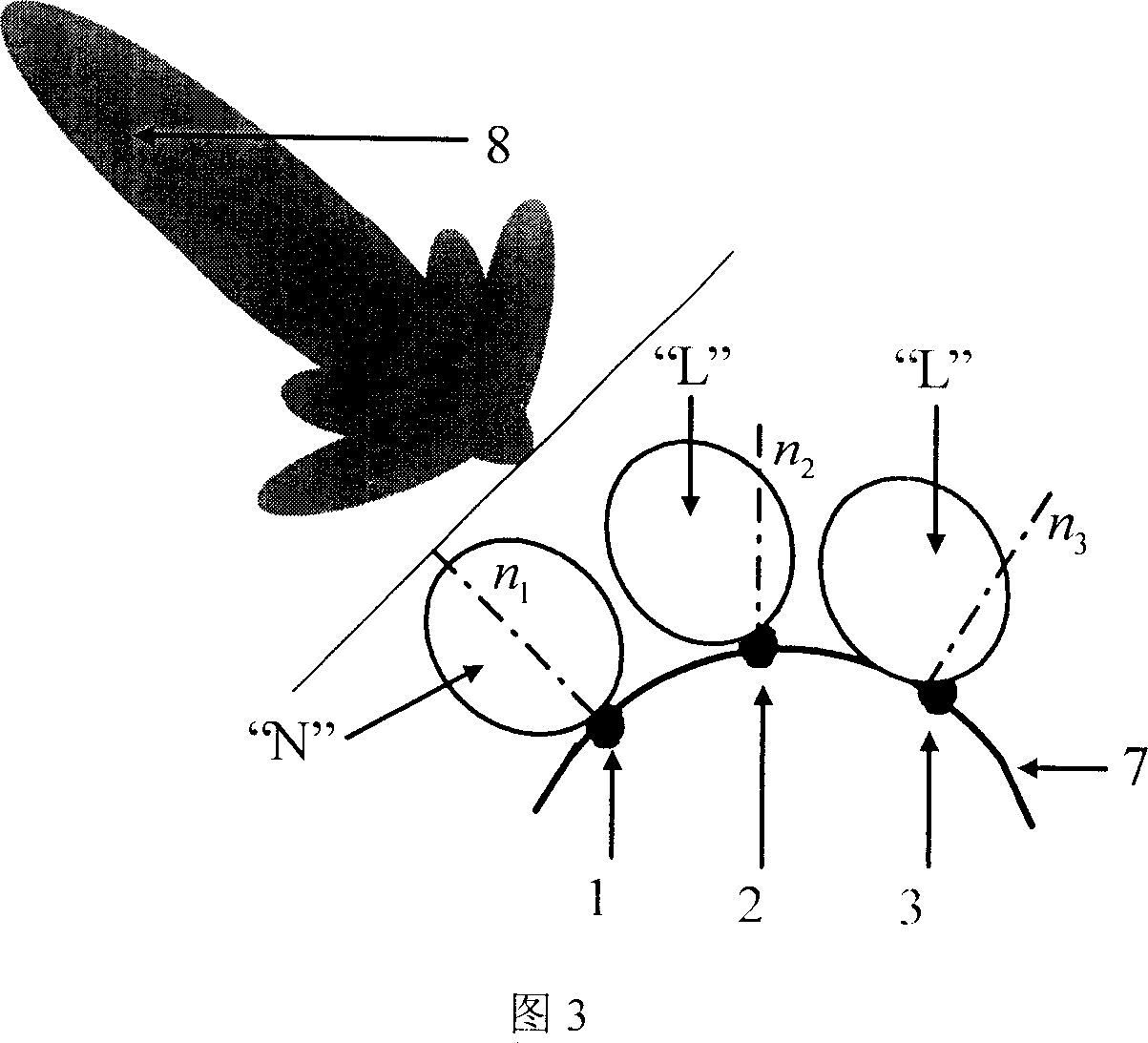
[0025] Fig. 1, Fig. 2 and Fig. 3 show three specific implementation manners of the pattern reconfigurable antenna array of the present invention.
[0026] For the situation shown in Figure 1, in order to keep the pattern orientation of each element in the array consistent with or close to the expected main beam orientation of the array pattern pattern, the pattern of the array element 1 should face the local normal direction n of the surface where it is located 1 The right side of the scan at a certain angle, adopt the state "R"; the pattern of the array element 2 should be reconstructed in the local normal direction n of the surface where it is located 2 The direction of the state "N" is adopted; the direction diagram of the array element 3 should face the local normal direction n of the surface where it is located 3 Scan the left side at an angle, adopting state "L".
[0027] Similarly, in Figure 2, in order to make the orientation of each element in the array consistent wi...
PUM
 Abstract
Description
Claims
Application Information