

Endoscope
An endoscope, a technology inside the tube, applied in the field of endoscope, can solve the problems of reduced insertability, reduced imaging function, and inability to process
- Summary
- Abstract
- Description
- Claims
- Application Information
AI Technical Summary
Problems solved by technology
Method used
Image

Examples
Embodiment 1
[0069] Embodiment 1 of the present invention will be described with reference to FIGS. 1 to 18 .
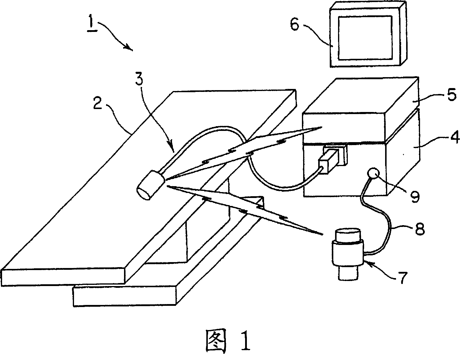
[0070]As shown in FIG. 1 , an endoscope system 1 according to Embodiment 1 of the present invention is composed of the following parts: an endoscope 3 for inspecting the inside of a body cavity of a patient (not shown) lying on an examination bed 2; An air supply and water supply suction unit (abbreviated as AWS unit) 4, which can be freely detachably connected to the endoscope 3 to perform air supply, water supply and suction control operations; an endoscope system control device that performs control processing for the endoscope 3, etc. 5; observation monitor 6, which displays the endoscope image etc. generated by the endoscope system control device 5; Various remote operations. The operation remote controller 7 is detachably connected to, for example, a connector 9 of the AWS unit 4 via a connection wire 8 .
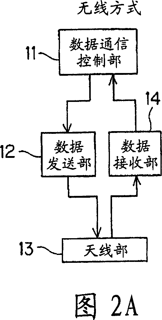
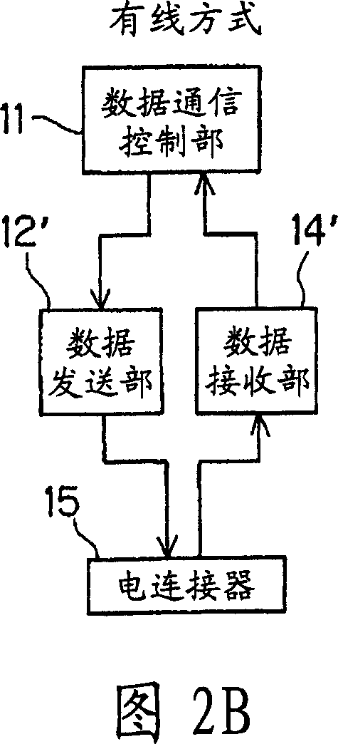
[0071] 2A to 2C show data communication methods used in this embo...
Embodiment 2
[0251] Next, Embodiment 2 of the present invention will be described with reference to FIGS. 19A to 21 .
[0252] Fig. 19A shows an endoscope 3B according to Example 2 of the present invention. In addition, FIG. 19B shows the front end side in FIG. 19A in a perspective view, thereby showing the internal structure of the front end side of the capsule part 22 .
[0253] This endoscope 3B is configured such that, instead of the four R-LEDs 39a, G-LEDs 39b, B-LEDs 39c, and IR-LEDs 39d as illumination units in the endoscope 3 shown in FIG. 3A , for example, two white LEDs are used. 39e, 39f, for routine observations in the visible region.
[0254] In addition, the endoscope 3B of the present embodiment is provided with, for example, an actuator for vibration in which a piezoelectric element is formed in an annular shape on the outer peripheral surface (or the inner peripheral surface) of the distal end portion of the capsule portion 22 ( The vibration unit) 131A, the vibration ac...
Embodiment 3
[0273] Next, Embodiment 3 of the present invention will be described with reference to FIGS. 23A to 24 .
[0274] 23A and 23B show an endoscope 3C according to Example 3 of the present invention. In this endoscope 3C, in the endoscope 3 shown in FIG. 3A , the rear end side of the outer casing 31 of the capsule portion 22 is also formed of a transparent member, and the base member 140 is disposed inside the rear end portion.
[0275] On the backside of the base member 140, for example, a white LED 141 for backlighting, and an objective lens 38B and a CCD 38B for imaging under the light of the white LED 142 are attached to form a backlighting and imaging unit 40B. This CCD 38B is also a CCD provided with a function that can change the gain in the CCD element.
[0276]In this way, in this embodiment, a rear lighting and imaging unit 40 for illuminating and imaging the front side (inside the body cavity) of the capsule unit 22 is provided on the front end side of the capsule unit...
PUM
 Abstract
Description
Claims
Application Information