A fluid separation device

A liquid separation and equipment technology, applied in mechanical equipment, separation methods, dispersed particle separation, etc., can solve the problems of difficult manufacturing technology, impossible to achieve with certain materials and manufacturing methods, etc.

Inactive Publication Date: 2007-03-07
REINZ DICHTUNGS
View PDF3 Cites 20 Cited by
  • Summary
  • Abstract
  • Description
  • Claims
  • Application Information

AI Technical Summary

Problems solved by technology

However, the one-piece manufacture of such long sections and draft tubes presents great manufactu

Method used


Image

  • A fluid separation device
  • A fluid separation device
  • A fluid separation device

Examples


Embodiment Construction

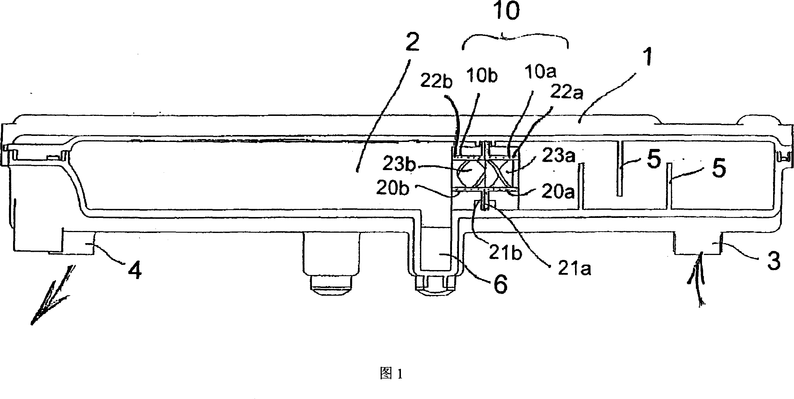
[0065] Figure 1 shows a cylindrical cowl 1 which can be attached to the cylindrical head of an internal combustion engine. The cylindrical hood 1 comprises a cavity 2 with an inlet 3 and an outlet 4 for gas. The blow-by gas now passing through the inlet 3 is blown out of the crankcase of the internal combustion engine into the cavity 2 and leaves this cavity 2 through the outlet 4 . The crankcase gases are separated from entrained oil or oil mist in this cavity 2 . This oil mist or separated oil collects in the siphon 6 and is carried back continuously or partially into the sump.

[0066] The impact plate 5 is arranged in the cavity 2 of the cylindrical hood 1 immediately after the inlet 3 . These impingement plates have the effect that a coarse separation of the oil droplets is already achieved on these impingement plates. The impingement plates 5 used for this are arranged offset, so that a labyrinth-like path of the gas through the impingement plates is produced.

[006...


PUM


Abstract

The present invention relates to a fluid separation device (10) for separating fluid, oil and oil spray from a gas. This fluid separation device (10) comprises a base carrier (21) in which fluid separator elements (20) in the form of flow-through tubes with worm-like segments (23) arranged therein, are integrated. The worm-like segments (23) at the same time form spiral flow paths (25) for the gas. They have a maximal length of half a pitch of the worm-like segment (23) so that the base carrier (21) together with the associated fluid separator elements (20) may be formed as one piece. Several base carriers may be arranged one after the other in a manner such that individual fluid separator elements of various base carriers form a common flow path for the gas.

Description

technical field [0001] The invention relates to a liquid separation device for separating a liquid and / or a liquid mist from a gas. Such separators are used, for example, to separate oil or oil mist from blow-by gases of internal combustion engines (crank casing gases, gases delivered into the cylinders in preparation for starting). Another area of ​​application for liquid separators is the field of electrochemical cells, especially PEM fuel cells, especially those suitable for H 2 O temperature range -- specifically between 20 degrees Celsius and 160 degrees Celsius -- for fuel cells to work. Background technique [0002] The power of such fuel cells is usually between a few watts and several kilowatts. Such PEM fuel cells (polymer electrolyte membrane fuel cells) have a proton-permeable polymer membrane. Such membranes need to have a certain moisture content so that they do not dry out and thus lose their functionality. For this purpose, the supplied reaction gas is hu...

Claims


Application Information

Patent Timeline
IPC IPC(8): B01D45/16H01M8/04F02C7/052F01M13/04
CPCF01M13/04Y10S55/05B01D45/16F01M2013/0427B01D45/12
Inventor 于尔根·瓦格纳迪特尔·格拉夫阿明·普拉斯卡凯-乌韦·莱姆克
Owner REINZ DICHTUNGS
Why Eureka
Try Eureka