Engine with an active mono-energy and/or bi-energy chamber with compressed air and/or additional energy and thermodynamic cycle thereof

A compressed air and engine technology, which is applied in the engine field of environmental heat energy recovery equipment, can solve the problems such as the reduction of the total efficiency of the machine

Inactive Publication Date: 2007-03-07
MDI MOTOR DEV INT SA
View PDF12 Cites 12 Cited by
  • Summary
  • Abstract
  • Description
  • Claims
  • Application Information

AI Technical Summary

Problems solved by technology

[0013] [13] In the operation of these "load expansion" engines, filling the chamber always implies a detrimental reduction in the overall efficiency of the machine

Method used


Image

  • Engine with an active mono-energy and/or bi-energy chamber with compressed air and/or additional energy and thermodynamic cycle thereof
  • Engine with an active mono-energy and/or bi-energy chamber with compressed air and/or additional energy and thermodynamic cycle thereof
  • Engine with an active mono-energy and/or bi-energy chamber with compressed air and/or additional energy and thermodynamic cycle thereof

Examples


Embodiment Construction

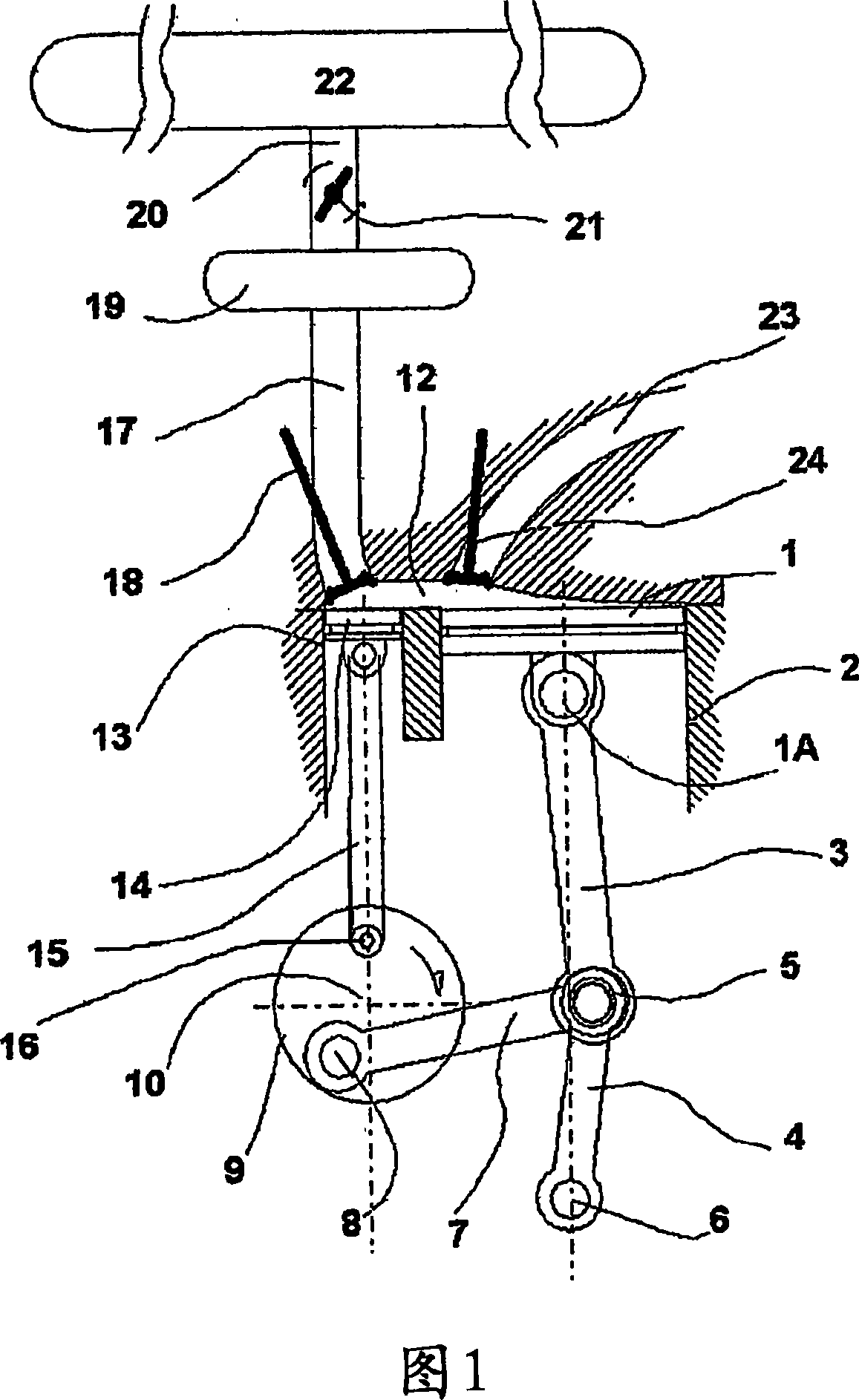
[0076] [76] Figure 1 shows an active chamber engine according to the invention, wherein the cylinder of the engine can be seen, in which slides said piston 1 (shown at its top dead center), said piston being driven by a Pressure lever control, sliding in a cylinder 2. Said piston 1 is connected by its shaft to the free end 1A of a pressure lever composed of an arm 3 articulated on a common axis 5 with the other arm 4 pivotally fixed on a stationary axis 6 . On the common shaft 5 with the two arms 3 and 4 is connected a control link 7 which is connected to the crank pin 8 of a crankshaft 9 which rotates about its axis 10 . When the crankshaft rotates, the control link 7 exerts a force on the common axis 5 of the two arms 3 and 4 of the pressure lever - thus allowing the piston 1 to move along the axis of the cylinder 2 , and during the working stroke, by rotating the crankshaft 9, the force exerted on said piston 1 is transmitted, thus causing the rotation of said crankshaft. ...


PUM


Abstract

The inventive engine uses a top dead center piston stop device. It is fed by compressed air, which is contained in a high-pressure storage tank, via a working capacity (19), which, in the bi-energy version, comprises a device for heating the air supplied by additional energy. The active expansion chamber consists of a variable volume or charge piston sliding in a cylinder, coupled to space above the engine piston (1) by means of a passage (12). When stoped at upper dead center, the pressurized air is admitted into the expansion chamber with the smallest volume thereof and, under the effect of thrust, increases the volume thereof by producing work; the expansion chamber is then kept at a maximum volume during expansion of the engine cylinder (2) driving back the engine piston (1) in its downward stroke, providing work of its own. During exhaust, the two pistons (1 and 13) travel in an upward stroke and simultaneously reach top dead center in order to resume a new cycle. The invention can be used with land vehicles, cars, buses, motor bikes, boats, auxiliary generator sets, cogeneration units and fixed station motors.

Description

technical field [0001] [01] The present invention relates to an engine which operates especially on compressed air or any other gas, and in particular to an engine which uses a piston stroke control device and an ambient heat recovery device which can be operated with single or dual energy sources, said piston stroke control A device is used to stop said piston at its top dead center for a period of time. Background technique [0002] [02] This contributor has applied for a number of patents concerning mechanization and its devices using compressed air for clean operation in cities and suburbs: [0003] [03] - WO 96 / 27737, WO 97 / 00655, [0004] [04] - WO 97 / 48884, WO 98 / 12062, WO 98 / 15440, [0005] [05] - WO 98 / 32963, WO 99 / 37885, WO 99 / 37885. [0006] [06] In order to implement these inventions, in the patent application WO 99 / 63206 - will introduce its content and also describe the engine piston stroke control method and equipment that make the piston stop at its top de...

Claims


Application Information

Patent Timeline
Patent Type & Authority Applications(China)
IPC IPC(8): F01B17/02F01B9/02F02B41/00F02B75/32
CPCF01B17/02F02B75/32F02B41/00F01B19/02F01B9/02
Inventor G·内格尔C·内格尔
Owner MDI MOTOR DEV INT SA
Why Eureka
Try Eureka