Hub unit for wheel

A hub unit and wheel technology, applied in the direction of wheels, axles, bearing components, etc., can solve problems such as increased torque or noise, shortened bearing life, track deformation, etc., to achieve the effects of preventing pressure failure, easy assembly, and small deformation

Inactive Publication Date: 2007-03-07
NSK LTD
View PDF6 Cites 2 Cited by
  • Summary
  • Abstract
  • Description
  • Claims
  • Application Information

AI Technical Summary

Problems solved by technology

When this deformation is large, it creates excessive pressure on the bearing and causes deformation of the track, which shortens the life of the bearing, increases torque or no

Method used


Image

  • Hub unit for wheel
  • Hub unit for wheel
  • Hub unit for wheel

Examples


Embodiment Construction

[0033] Hereinafter, a wheel hub unit according to an embodiment of the present invention will be described with reference to the accompanying drawings.

[0034] In this specification, the flange side of the wheel hub unit on which the wheel is mounted and which generally faces the outside of the vehicle body in the state where the wheel hub unit is mounted on the vehicle body is referred to as the outer side, and the opposite side toward the center of the vehicle is referred to as the outer side. inside.

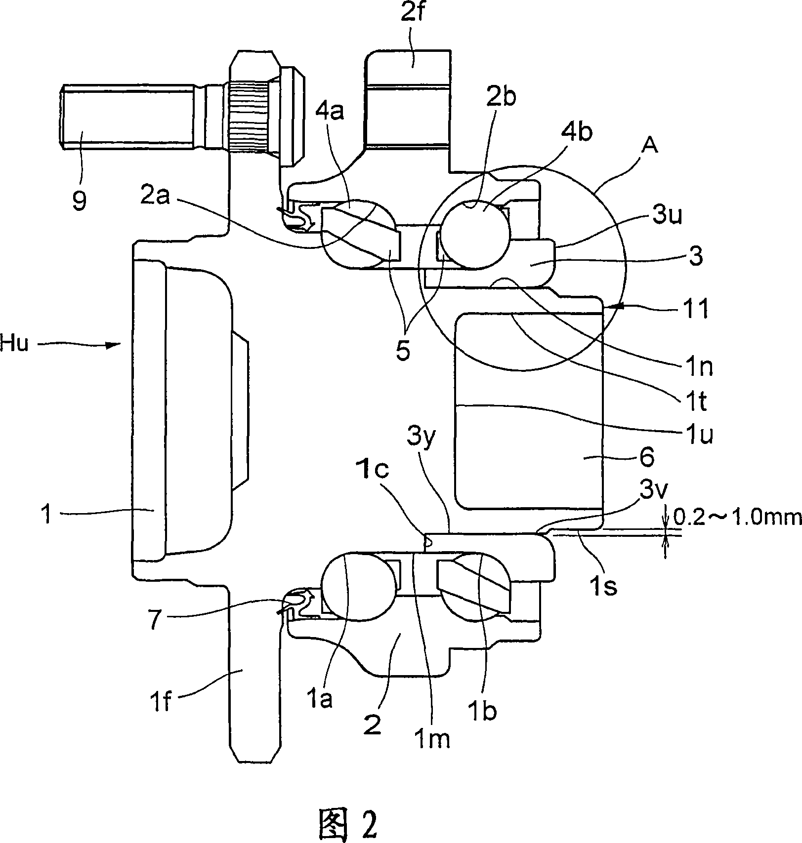
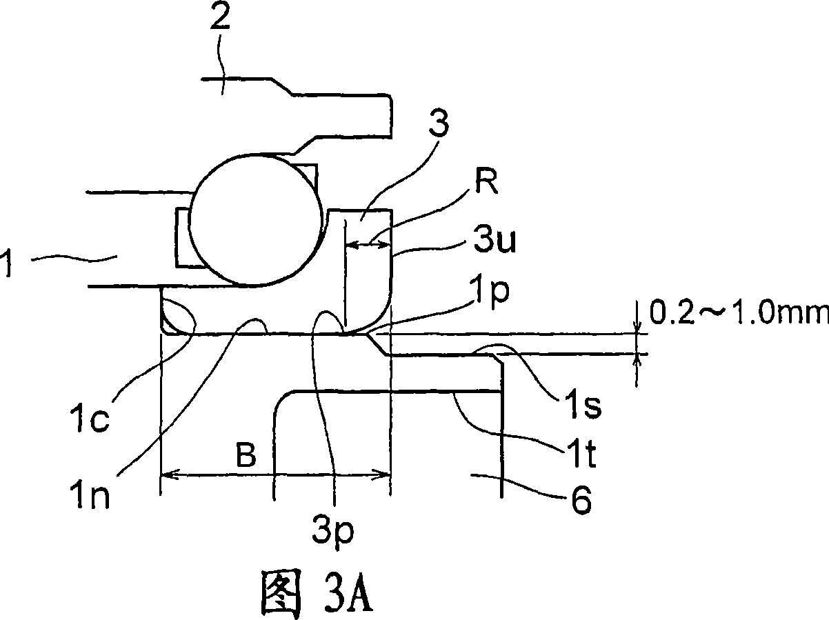
[0035] Next, a first embodiment of the present invention will be described with reference to FIGS. 1 and 3A-3C.

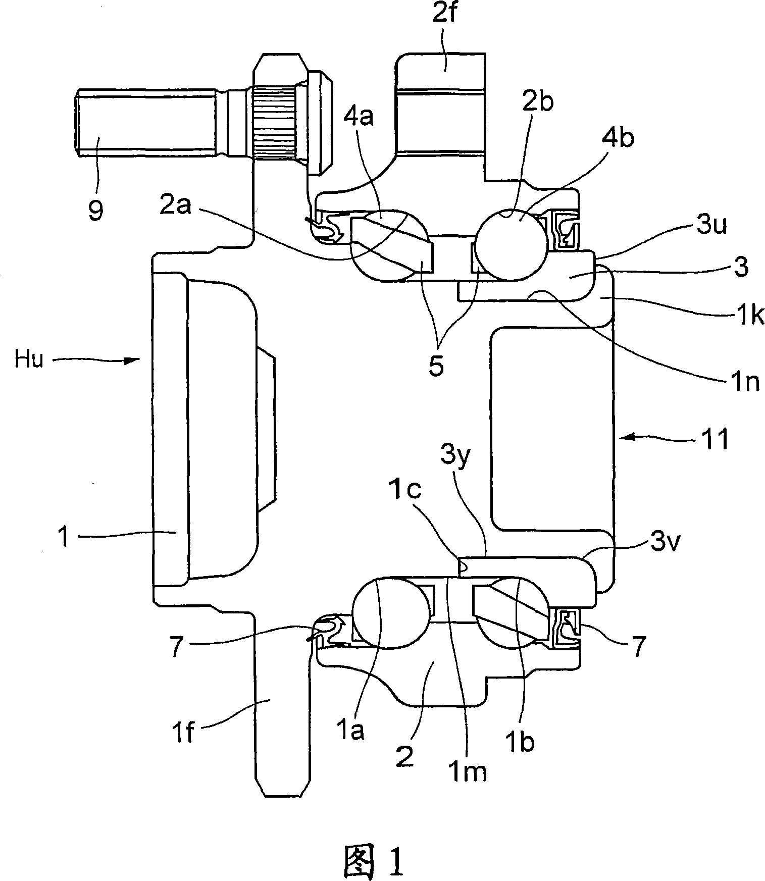
[0036] FIG. 1 is a cross-sectional view of a wheel hub unit Hu according to the first embodiment.

[0037] In FIG. 1, the hub 1 is formed with a flange 1f for mounting a wheel (not shown) on the outer end side thereof. The first bearing rail 1a is directly provided on the flange-side outer peripheral surface, which is a part of the outer peripheral surface 1m o...


PUM


Abstract

A hub unit for a wheel, having an outer ring, a hub, an inner element, and rolling bodies. The outer ring has two rows of bearing raceways on its inner periphery. The hub has a wheel installation flange on the outer end side, has an end section on the vehicle center side in the axial direction, and has, integrally or as a separate body, on its outer periphery a first bearing raceway corresponding to a bearing raceway on the vehicle outer end side in the axial direction of the outer ring. The inner ring element is fitted on the end section side of the hub, has on its outer periphery a second bearing raceway facing the bearing raceway on the vehicle center side in the axial direction of the outer ring, and fixed to the end section of the hub by plastically deforming the end section radially outward. The rolling bodies are interposed between the two bearing raceways of the outer ring and the first and second bearing raceways. The outer diameter of the plastically deformed section of the end section is set smaller than the diameter of that section of the inner ring element which is fitted on the hub, the start point of the small diameter section is positioned between the start point of a chamfered section on the inner peripheral surface of the inner ring element and a vehicle center side end surface of the inner ring element, and the end section is plastically deformed radially outward to fasten and fix the inner ring element. Alternatively, a continuous circumferential groove can be provided close to the chamfered section of an inner end section on the inner peripheral surface of the inner ring element.

Description

technical field [0001] The present invention relates to a wheel hub unit for a vehicle. In particular, the present invention relates to a vehicle hub unit in which inner ring elements fitted on the hub are fastened and fixed to the hub by riveting / caulking (caulking) the end portion of the hub on the vehicle center side. Background technique [0002] In the hub unit in which the inner ring element is fixed by riveting the vehicle center side end of the hub, the riveting tool plastically deforms the end to be riveted in such a manner as to extend radially outward, so that the inner ring element is thus The riveted plastic deformation portion is fastened and fixed. During this process, there is a risk that the inner ring element and / or the hub may deform causing a change in the dimensions of the track on the inner ring element or deformation of the shape of the track surface, which can lead to a deterioration in the performance of the hub unit. [0003] In order to avoid def...

Claims


Application Information

Patent Timeline
IPC IPC(8): F16C35/063B60B35/02F16C19/18B60B35/18F16C43/04
Inventor 千布刚敏竹原彻杉万朋治汤川谨次
Owner NSK LTD
Why Eureka
Try Eureka