Constant velocity joint

A technology of constant velocity universal joints and guide grooves, applied in elastic couplings, mechanical equipment, couplings, etc., can solve the problem of increased displacement of roller components 14, limited inclination angle θ, damage to constant velocity Problems such as knuckle rotation driving force transmission function, to achieve the effect of reducing stress, improving degree of freedom, and high degree of design freedom

Inactive Publication Date: 2007-03-07
HONDA MOTOR CO LTD
View PDF3 Cites 9 Cited by
  • Summary
  • Abstract
  • Description
  • Claims
  • Application Information

AI Technical Summary

Problems solved by technology

At this time, as the inclination angle θ of the inner member 6 increases, the amount of displacement of the roller member 14 increases. Therefore, if the trunnion 10 is not set to be long enough in advance, the roller member 14 will be in contact with the trunnion 10. The base end portion 10a interferes so that the inclination angle θ is limited
On the other hand, if the trunnion 10 is lengthened, the diameter of the outer member 4 is also increased, resulting in an increase in the size of the constant velocity joint 2
[0018] Furthermore, in the roller mechanism 26 shown in FIG. 22, for example, when the snap ring 24 is disengaged from the circumferential groove 23 for some reason, the centrifugal force generated by the rotational motion of the constant velocity joint is loaded on the roller mechanism 26. The needle roller 27 between the cylindrical inner peripheral surface 22 of the roller 21 and the support ring 29 may fly out from the inside of the roller 21, impairing the rotation driving force transmission function of the constant velocity universal joint.

Method used


Image

  • Constant velocity joint
  • Constant velocity joint
  • Constant velocity joint

Examples


Embodiment Construction

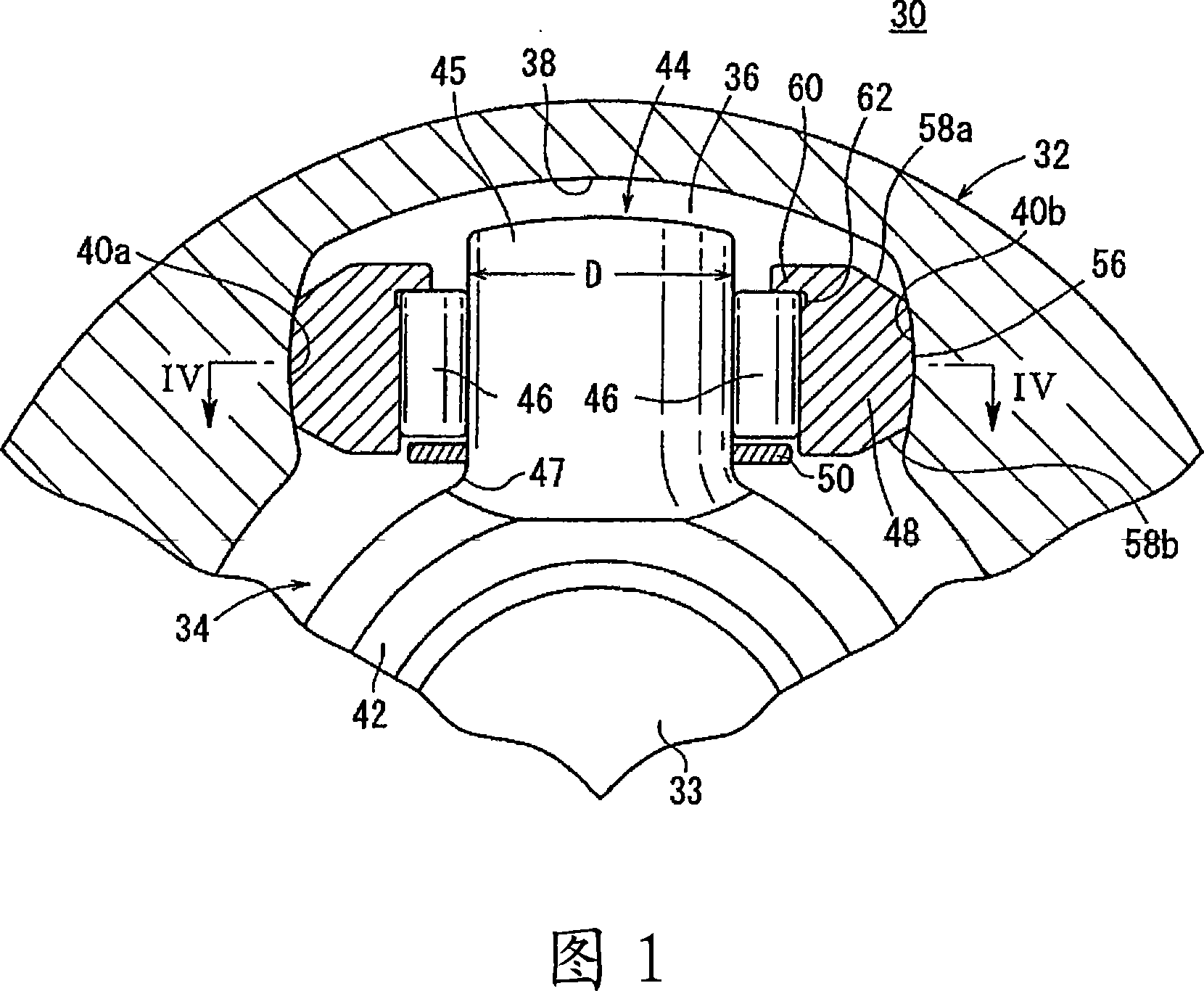
[0064] FIG. 1 is a longitudinal sectional view of main parts along a direction perpendicular to the axis of a constant velocity joint 30 according to a first embodiment of the present invention. The constant velocity joint 30 mainly includes: a cylindrical outer member 32 integrally connected to one end of one transmission shaft (not shown) and having an opening; The inner part 34 in the inner space portion of the outer part 32 .

[0065] Three guide grooves 36 extending in the axial direction and spaced 120 degrees from each other around the axis are formed in the inner space portion of the outer member 32 . The guide groove 36 includes: a top plate portion 38 having a gently curved cross section; and sliding portions 40 a , 40 b facing each other on both sides of the top plate portion 38 and having an arcuate cross section.

[0066] An annular tripod 42 constituting the inner member 34 is externally fitted on the transmission shaft 33 . Three trunnions 44 protruding toward...


PUM


Abstract

The present invention provides a constant velocity universal joint, in which a ring member (50) is mounted on a cylindrical portion (45) of a trunnion (44), and rollers of a needle bearing (46) are held on the inner peripheral portion The part (48) is mounted on the cylindrical part (45). The needle bearing (46) is held with a predetermined gap between a flange portion (60) formed at one end of the roller member (48) and an annular member (50) attached to the trunnion (44). In addition, the gap (X) between the needle bearing (46) and the ring member (50) is set to satisfy the following relationship: X>R / 2·(1 / cos θmax-1), where R represents the roller The radius of rotation of the center of the sub-part (48) relative to the central axis of the outer part 32, θmax represents the maximum inclination angle of the inner part (34).

Description

technical field [0001] The present invention relates to a constant velocity joint that connects one propeller shaft to another propeller shaft in, for example, a driving force transmission portion of an automobile. Background technique [0002] Conventionally, constant velocity joints are used in drive force transmission parts of automobiles, which connect one propeller shaft to another propeller shaft to transmit rotational force to each axle. [0003] FIG. 20 shows a partial cross section of such a conventional constant velocity joint 2 (see Japanese Patent Application Laid-Open No. 10-184717). [0004] This constant velocity joint 2 includes: a cylindrical outer member 4 connected to one transmission shaft; and an inner member 6 inserted into the outer member 4 and connected to the other transmission shaft. Three guide grooves 8 extending in the axial direction are formed on the inner peripheral surface of the outer member 4 . On the other hand, the inner member 6 has t...

Claims


Application Information

Patent Timeline
Patent Type & Authority Applications(China)
IPC IPC(8): F16D3/205
Inventor 川胜勉小仓尚宏柴田直人中尾彰一青山友纪
Owner HONDA MOTOR CO LTD
Why Eureka
Try Eureka