Variable valve device of engine

A technology for engine valves and valve devices, applied to valve devices, engine components, machines/engines, etc., can solve problems such as increased costs, achieve the effects of increasing processing costs, reducing costs, and improving adjustment operation efficiency

Inactive Publication Date: 2013-04-10
HONDA MOTOR CO LTD
View PDF2 Cites 0 Cited by
  • Summary
  • Abstract
  • Description
  • Claims
  • Application Information

AI Technical Summary

Problems solved by technology

[0004] However, in the technology of the above-mentioned proposal (Japanese Patent Application No. 2007-256790), in order to use the actuator to move the movable part by a predetermined amount, it is necessary to improve the dimensional accuracy of each part from the actuator to the movable part via the rotating rod, which leads to Issues with high costs

Method used


Image

  • Variable valve device of engine
  • Variable valve device of engine
  • Variable valve device of engine

Examples


Embodiment 1

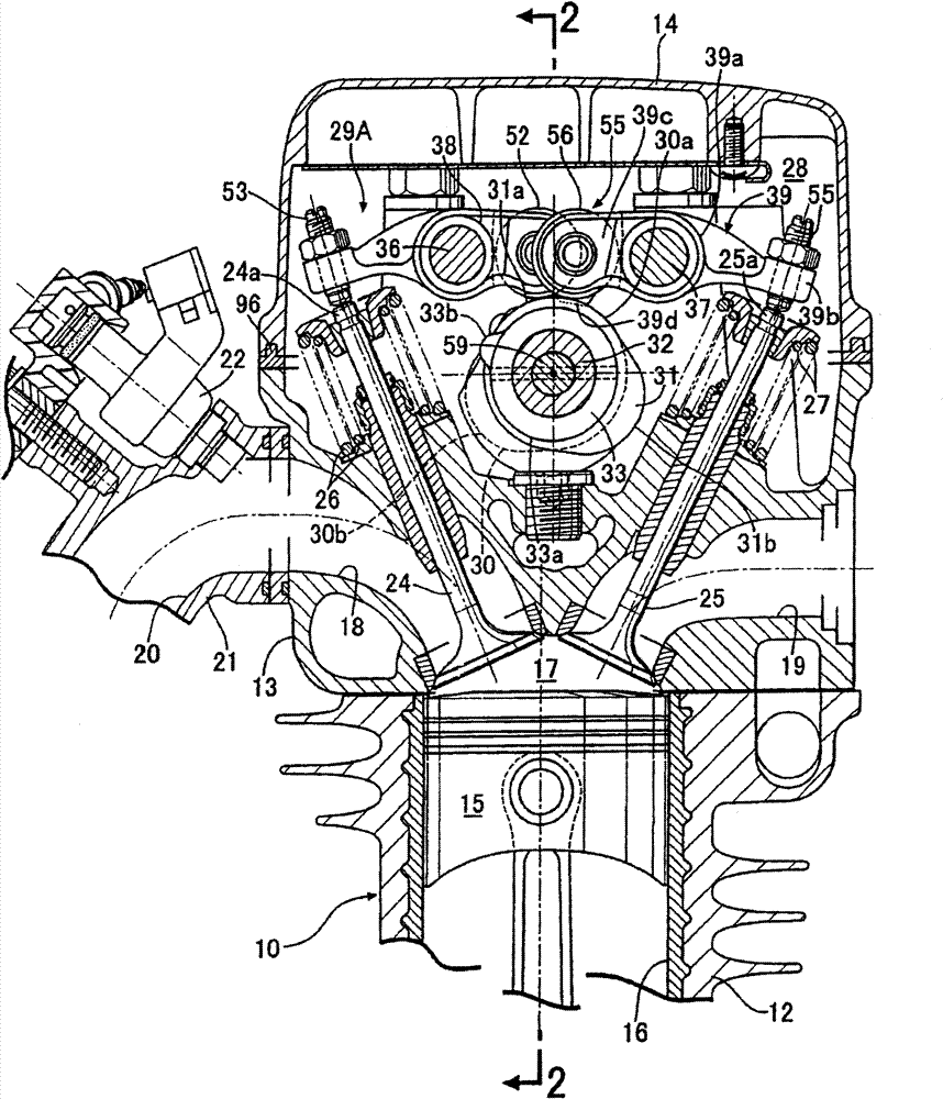
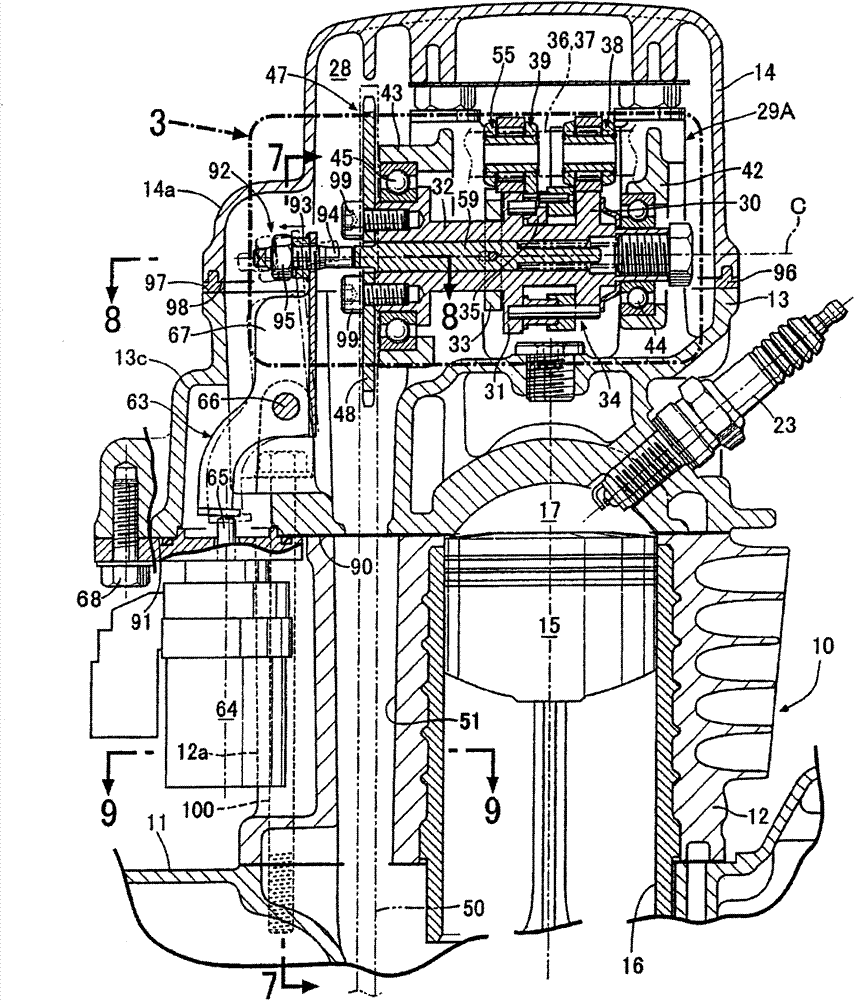
[0050] Below, refer to Figure 1 to Figure 12 Example 1 of the present invention will be described. First, in figure 1 and figure 2 Among them, the engine body 10 of the engine is, for example, an engine mounted on a motorcycle, and the engine body 10 combines a crankcase 11 , a cylinder block 12 , a cylinder head 13 , and a head cover 14 as a plurality of engine body components. The cylinder block 12 has a cylinder bore 16 in which the piston 15 is slidably fitted, is coupled to the crankcase 11 , and a cylinder head facing the combustion chamber 17 at the top of the piston 15 is formed between the cylinder block 12 and the cylinder block 12 . 13 is combined with the cylinder block 12 , and from the side opposite to the cylinder block 12 , the head cover 14 is combined with the cylinder head 13 .

[0051]The cylinder head 13 is provided with an air inlet 18 open to one side thereof and an exhaust port 19 opened toward the other side of the cylinder head 13 to form an air ...

Embodiment 2

[0108] refer to Figure 13 and Figure 14 Example 2 of the present invention will be described. Portions corresponding to those in Embodiment 1 are shown with the same reference numerals, and detailed descriptions are omitted.

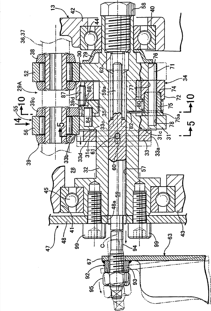
[0109]The movable valve mechanism 29B has: a camshaft 32, which is arranged between the intake valve 24 and the exhaust valve 25, and is provided with an intake cam 30 and an exhaust cam 31; The cam profile of the air cam 31 is installed on the outer periphery of the camshaft 32 in a manner that is movable in the axial direction but not relatively rotatable; a decompression mechanism 34 is used to clamp the exhaust cam 31 between it and the The sliding cam 33 is mounted on the camshaft 32; the intake side and exhaust side rocker shafts 36, 37 have axes parallel to the camshaft 32 and are supported by the cylinder head 13; the intake side The rocker arm 38 is driven by the intake cam 30 to drive the intake valve 24 to open and close and is swayably s...


PUM


Abstract

The invention provides a variable valve device of an engine, including a movable valve mechanism which can change the action characteristic of an engine valve to drive the engine valve to open and close according to the action of a movable member doing linear motion; an actuating mechanism which generates a power for driving the movable valve to act to change the action characteristic of the engine valve; and a rotation rod which transmits the output of the actuating mechanism to the movable member. The variable valve device does not need improving the processing precision and has low cost. An adjusting mechanism (92) which adjusts the movement amount of the movable member (59) with respect to the actuating mechanism (64) is arranged on a connection portion of the rotation rod (67) and the movable member (59) or the connection portion of the rotation rod and the actuating mechanism (64).

Description

technical field [0001] The present invention relates to a variable valve device for an engine, comprising: a moving valve mechanism having a movable member capable of linear motion, and capable of driving the engine valve to open by changing the operating characteristics of the engine valve according to the motion of the movable member closing; an actuator, which generates power to actuate the valve actuator to change the operating characteristics of the engine valve; a rotating rod, which transmits the output of the actuator to the movable part. Background technique [0002] Patent Document 1 discloses a variable valve device for an engine in which the operating characteristics of an engine valve can be changed by moving a valve cam in the axial direction by an actuator. The cam is provided on the camshaft so as to be non-rotatable and relatively movable in the axial direction. In the variable valve device as described above, since the large-sized movable valve cam itself i...

Claims


Application Information

Patent Timeline
Patent Type & Authority Patents(China)
IPC IPC(8): F01L13/08
Inventor 山西辉英石川秀男寺田保男藤原一夫千叶一彦中沟大和
Owner HONDA MOTOR CO LTD
Why Eureka
Try Eureka