Design method of three-dimensional optical lens and lens

A design method, three-dimensional optical technology, applied in optics, lenses, optical components, etc.

Active Publication Date: 2007-03-14
TSINGHUA UNIV
View PDF0 Cites 19 Cited by
  • Summary
  • Abstract
  • Description
  • Claims
  • Application Information

AI Technical Summary

Problems solved by technology

[0007] The invention solves the problem of designing an optical system according to the specific illuminance distribution in the a

Method used


Image

  • Design method of three-dimensional optical lens and lens
  • Design method of three-dimensional optical lens and lens
  • Design method of three-dimensional optical lens and lens

Examples


Embodiment Construction

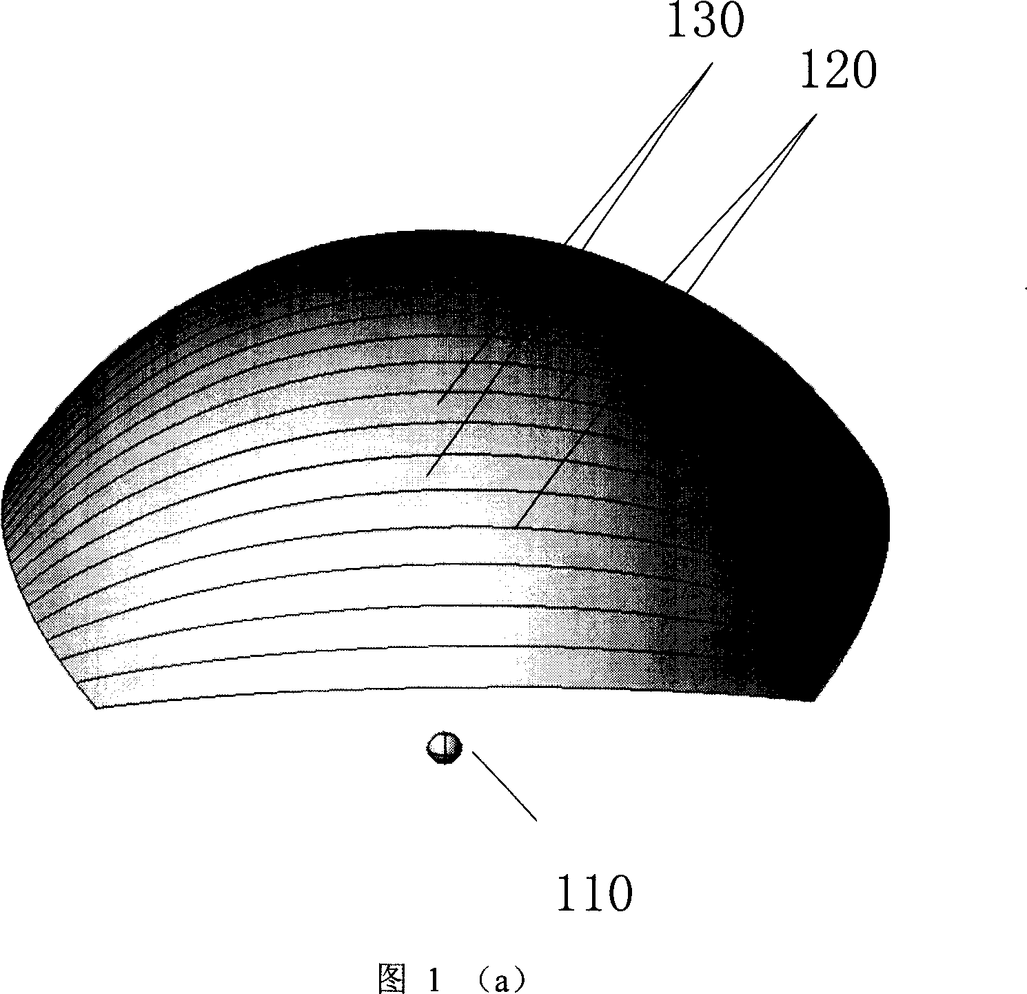
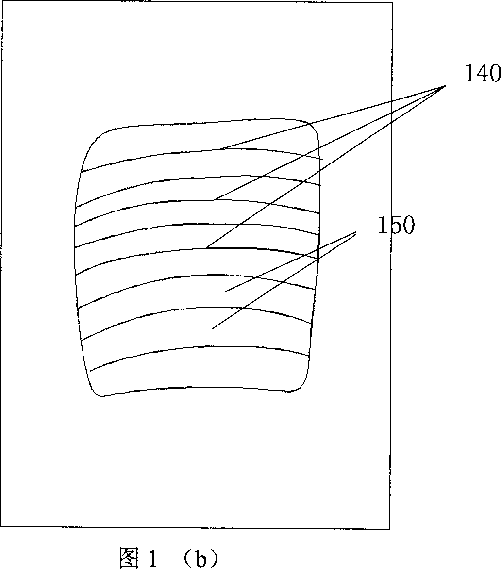
[0100] The present invention is based on the principle of energy conservation, divides the energy of the light output direction of the point light source and the energy of the illuminance plane first, and makes a one-to-one correspondence between the energy of the two in the form of several discrete points, and then according to this correspondence, superimposed The coordinates of the discrete data points on the surface of the optical system corresponding to the relationship between the two energies and the direction of the light are obtained by solving it, thereby determining the shape of the lens surface.

[0101] The energy unit division method was first used to form a given light intensity distribution, see (W.A.Parkyn, "Designing Illumination Lens Using the Method of External Differential Geometry", Proc.SPIE, vol 3482, pp.191-193(1998) .), in the method proposed by the present invention, the energy unit division method is further extended to a point-to-point mapping relat...


PUM


Abstract

The 3D optical lens design method comprises: based on law of conservation of energy, dividing out some sub-areas as the light source energy equal to illuminant plane energy; selecting one point any of the point in one emergence line and corresponding equal-energy illuminant plane points as the initial point for target lens; iterative solving coordinate and normal vector for every discrete point to determine the lens surface. Compared with prior art, this invention is convenient and high efficient, and can save energy for wide application.

Description

technical field [0001] A design method of a three-dimensional optical lens and the lens relate to the technical field of optical design of three-dimensional given illuminance distribution in non-imaging optics. technical background: [0002] The lens of the traditional imaging optical design usually has rotational symmetry, which is used to image the point of the object plane on the image plane after passing through the lens. The lens design of traditional optics pays more attention to the preservation of image information during the imaging process, and the light energy transmission efficiency is placed in a secondary position, so the designed lens usually has a relatively low transmission efficiency. [0003] Non-imaging optics is a new branch of optics that has been gradually developed abroad since the 1970s, specializing in the study of energy transmission of light. Non-imaging optics first mainly studied the collection and utilization of solar energy, that is, the prob...

Claims


Application Information

Patent Timeline
IPC IPC(8): G02B27/00G02B3/00
Inventor 罗毅钱可元王霖韩彦军
Owner TSINGHUA UNIV
Why Eureka
Try Eureka