Tri-state tree representing and location method of network element object in network optimization system

A technology of network element objects and positioning methods, which is applied in transmission systems, digital transmission systems, data exchange networks, etc., can solve problems such as cumbersome operations, and achieve the effects of improving positioning efficiency, convenient operation, and clear structure

Inactive Publication Date: 2007-03-14
ZTE CORP
View PDF0 Cites 13 Cited by
  • Summary
  • Abstract
  • Description
  • Claims
  • Application Information

AI Technical Summary

Problems solved by technology

As shown in Figure 2, it takes nine clicks to select nine base stations. If the user needs to select hundreds of base stations, the operation will be very cumbersome

Method used


Image

  • Tri-state tree representing and location method of network element object in network optimization system
  • Tri-state tree representing and location method of network element object in network optimization system
  • Tri-state tree representing and location method of network element object in network optimization system

Examples


Embodiment Construction

[0037] The specific implementation of the method of the present invention will be further described in detail below with reference to the accompanying drawings.

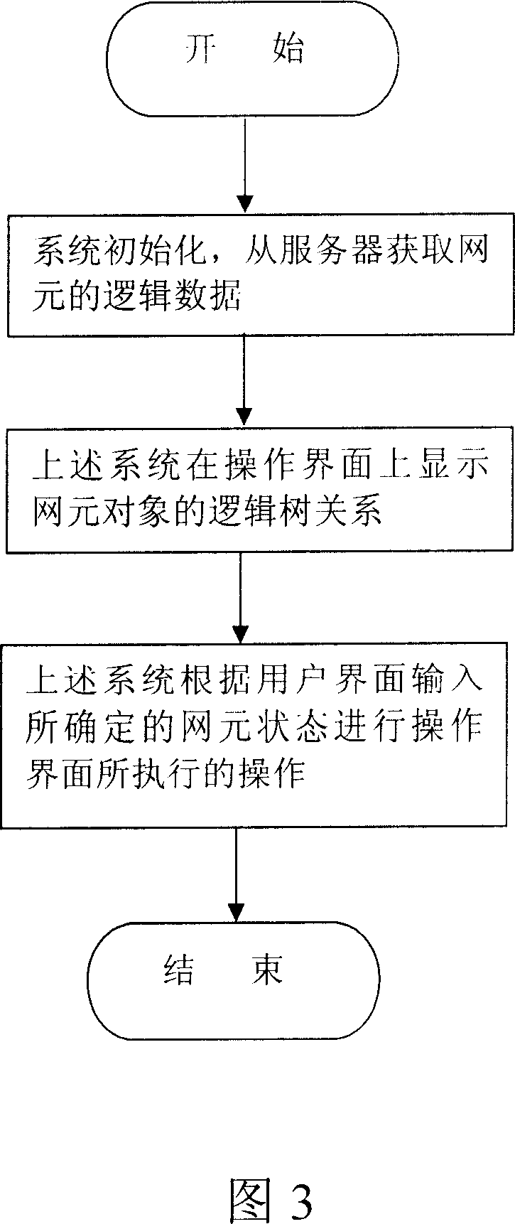
[0038] FIG. 3 is a flow chart of the operation of the method of the present invention. As shown in Figure 3, it mainly includes the following steps:

[0039] Step 1: The system is initialized, and the logical data of the network element is obtained from the server;

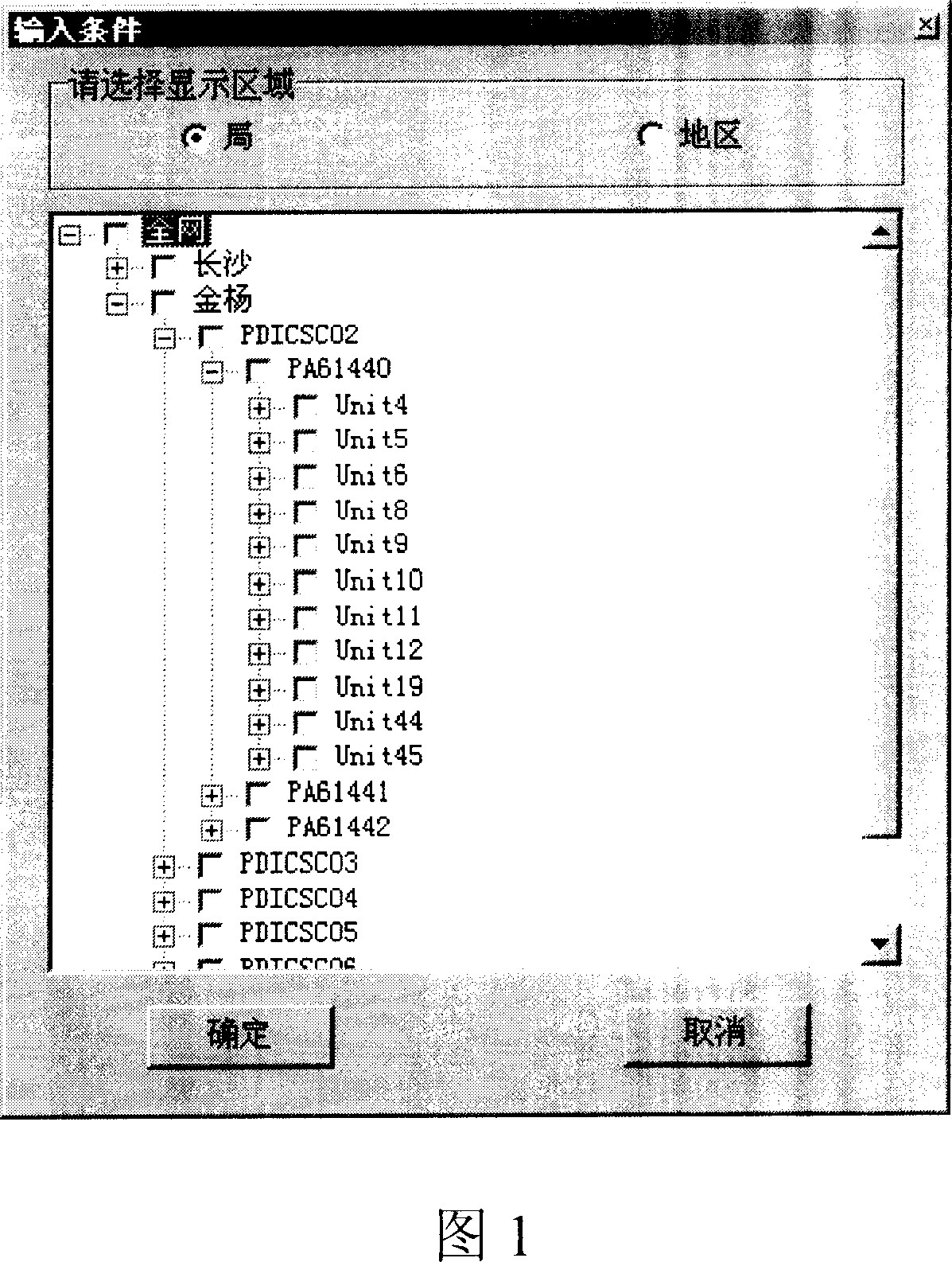
[0040] Step 2: the above-mentioned system displays the logical tree relationship of the network element objects on the operation interface; and

[0041] Step 3: The above-mentioned system performs the operation performed by the operation interface in the above-mentioned step 2 according to the network element state determined by the user interface input.

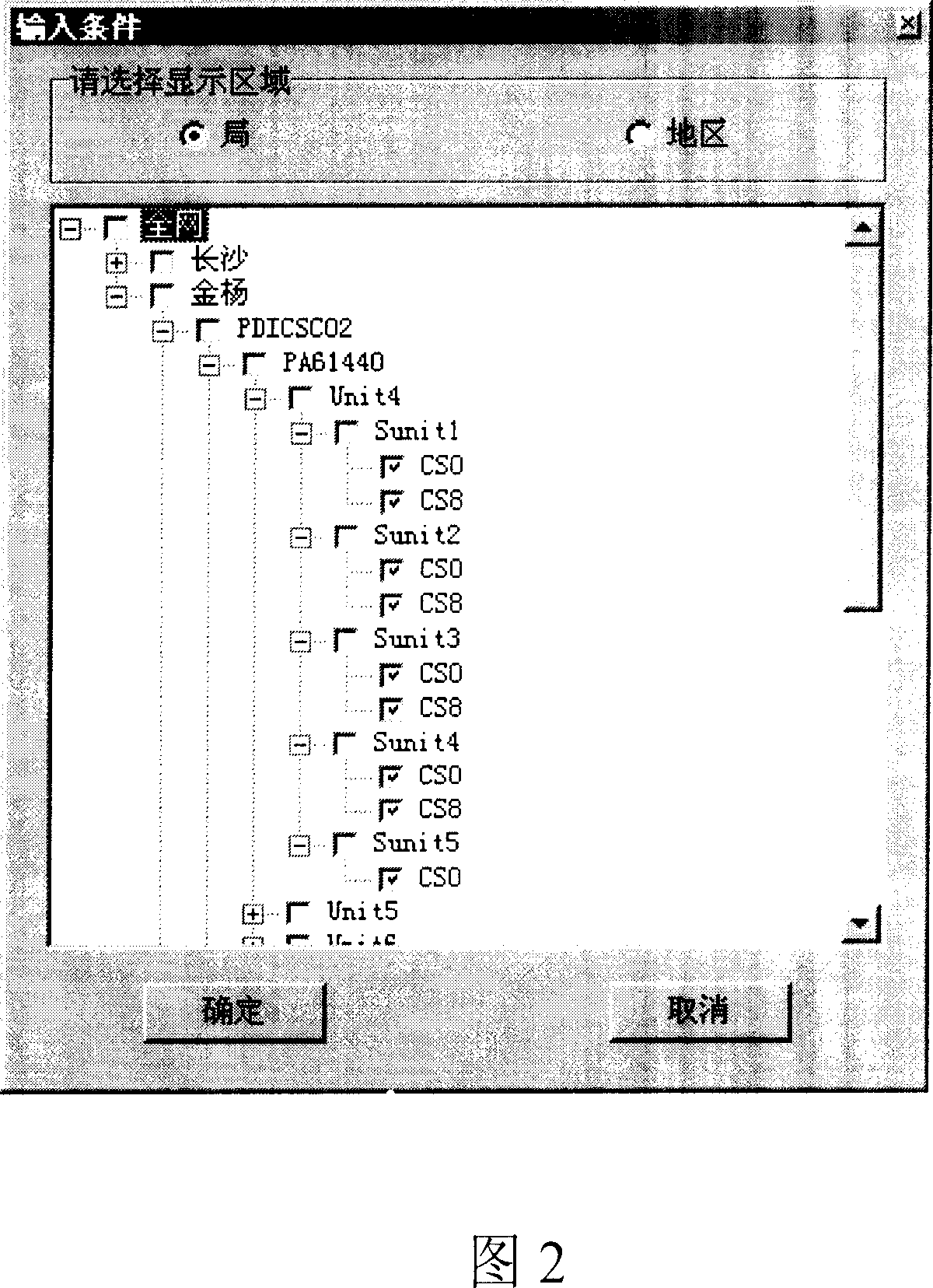
[0042] Wherein, the principle of determining the state of the network element according to the user interface input in the above step 3 includes:

[0043] 1) If the top-level parent node is "selecte...


PUM


Abstract

This invention provides one network optimization network subject three tree appearing and positioning method, which comprises steps of system initiating, getting network logic data, displaying element logic tree relationship and inputting network by user interface for above operation interface wherein, the above three trees refer to one tree structure each point including select, semi-sleet and non select status.

Description

technical field [0001] The invention relates to a method for displaying and locating hierarchical objects, in particular to the presentation of logical relationships between network element equipment and base station equipment in the field of wireless communications, and in particular to a network optimization system (hereinafter referred to as a "network optimization system"). A three-state tree presentation and positioning method for network element objects. Background technique [0002] In the wireless network optimization system and wireless network management system, it is often necessary to deal with the display of some hierarchical objects, such as network elements, base station controllers, and cell stations (hereinafter referred to as CS), which are objects with a certain hierarchical relationship. In these systems, it is necessary to select these hierarchical structure objects first, and then perform subsequent operations, such as traffic query, fault query and loa...

Claims


Application Information

Patent Timeline
Patent Type & Authority Applications(China)
IPC IPC(8): H04L12/24G06F17/30
Inventor 张丽静李伟民
Owner ZTE CORP
Why Eureka
Try Eureka