Device for filling tubes, containers and the like with bulk materials

A loose material, test tube technology, used in loading/unloading, transportation and packaging, chemical instruments and methods, etc., can solve the problem of wasting time, and achieve the effect of saving a lot of cost and time

Inactive Publication Date: 2007-03-14
BASF AG
View PDF3 Cites 0 Cited by
  • Summary
  • Abstract
  • Description
  • Claims
  • Application Information

AI Technical Summary

Problems solved by technology

Furthermore, moving the device manually is a waste of time

Method used


Image

  • Device for filling tubes, containers and the like with bulk materials
  • Device for filling tubes, containers and the like with bulk materials

Examples


Embodiment Construction

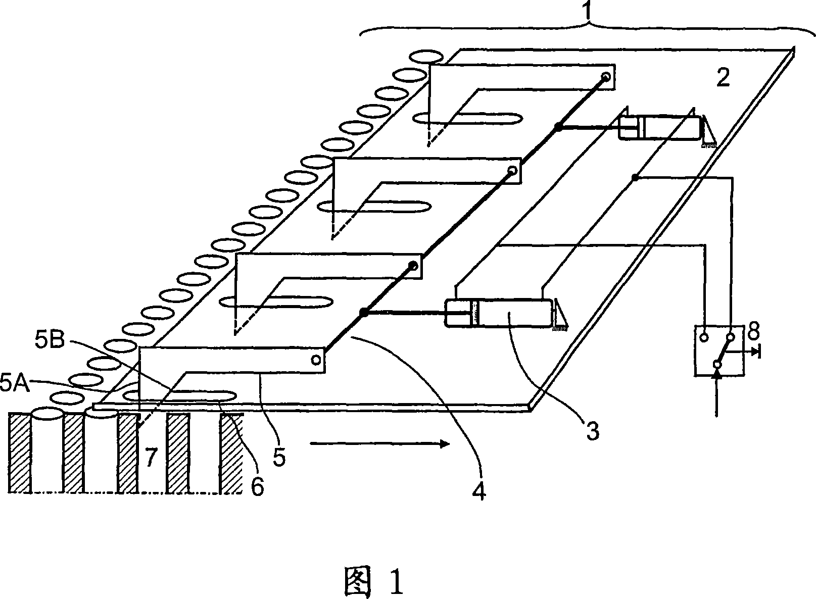
[0031]The conveying device 1 generally comprises a base plate 2 on which two piston-cylinder units 3 are fixed. The push rod of the piston-cylinder unit is connected to the delivery claw 5 via the connecting rod 4 . The free ends of the transport claws 5 protrude through openings 6 in the bottom plate into test tubes 7 of the shell and tube reactor. The transport claw 5 has a straight side 5A and a beveled side 5B. The repositioning of the delivery means is triggered by means of the pneumatic button 8 . When the button is pressed, the jaw 5 is pulled back from its rest position by means of the push rod of the piston-cylinder unit 3 . Due to (the presence of) the beveled edge 5B, this movement of the transport jaw does not stop at the tube edge; the transport jaw slides over the test tube edge and the free jaw falls into the next column of test tubes. When button 8 is pressed again, cylinder 3 moves in reverse. However, due to (the presence of) the straight edge 5A, the cla...


PUM


Abstract

The invention relates to a device for charging bulk materials, in particular small catalysts in tubes, containers and the like comprising a plurality of charging units and a transport unit (1) for moving said charging units. The aim of said invention is to carry out the charging units in a more reliable and accurate manner. For this purpose, the inventive transport unit comprises a forwardly and backwardly movable bottom (2), at least one cylinder/piston unit (3) which is fixed thereto and one or several transport claws (5) which are functionally associated to the cylinder/piston unit, are rotatable about a common axis and whose free ends are projected across recesses (6) embodied in the bottom in tubes (7), containers and the like. The length of the recesses in the direction of the bottom displacement is equal to or greater than the stroke of the cylinder/piston unit.

Description

technical field [0001] The invention relates to a device for introducing bulk material into test tubes, containers and the like, having a plurality of feeding units and a conveying device capable of simultaneously moving said feeding units. Background technique [0002] Shell and tube reactors are often used to perform chemical reactions in which gases are catalyzed. Examples that may be mentioned are, inter alia, the selective oxidation of hydrocarbons over a fixed bed (Festbett) of catalytic bulk material. Since these reactions are exothermic, the heat of reaction must be removed from the reactor as efficiently as possible. If the reaction is carried out in an uncontrolled manner, the production of undesirable by-products increases and expensive raw materials are destroyed. A known method of removing heat very efficiently is to fill very small diameter test tubes with a catalyst and to deliver a coolant through the gaps between the test tubes. The usual diameter of the ...

Claims


Application Information

Patent Timeline
Patent Type & Authority Applications(China)
IPC IPC(8): B01J8/06B01J8/00B65G47/18
CPCB01J8/003B01J2208/00752B01J8/067B01J8/06B01J8/02B65G65/32B01J8/00
Inventor K-H·斯托克塞芬H-J·欣德根W·拉梅尔
Owner BASF AG
Why Eureka
Try Eureka