Fluid machine

A kind of fluid machinery and fluid technology, applied in the field of expander, can solve problems such as increase in enthalpy and decrease in refrigeration capacity

Active Publication Date: 2007-03-14
DAIKIN IND LTD
View PDF1 Cites 7 Cited by
  • Summary
  • Abstract
  • Description
  • Claims
  • Application Information

AI Technical Summary

Problems solved by technology

In particular, when the above-mentioned fluid machine is applied to an air conditioner or the like that performs a refrigeration cycle, since the enthalpy of the refrigerant sent from the expansion mechanism to the evaporator increases, the refrigeration capacity decreases. bad influence

Method used


Image

  • Fluid machine
  • Fluid machine
  • Fluid machine

Examples


Embodiment approach 1

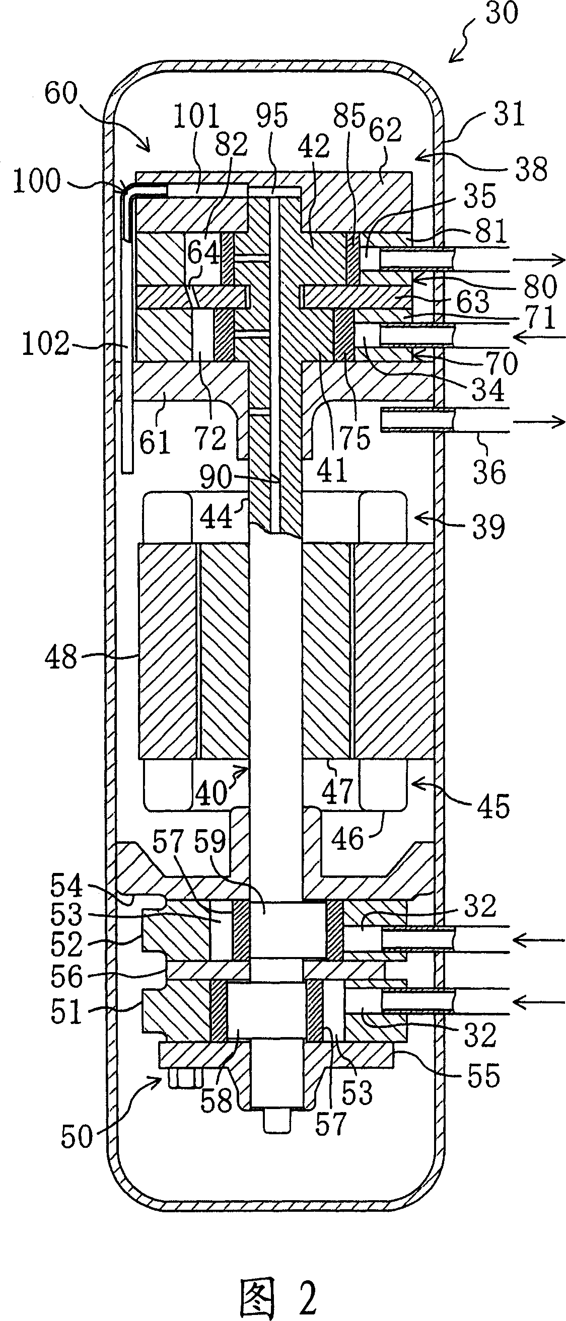
[0060] The first embodiment of the present invention will be described. The air conditioner 10 of this embodiment has a compression / expansion unit 30 as the fluid machine of the present invention.

[0061]

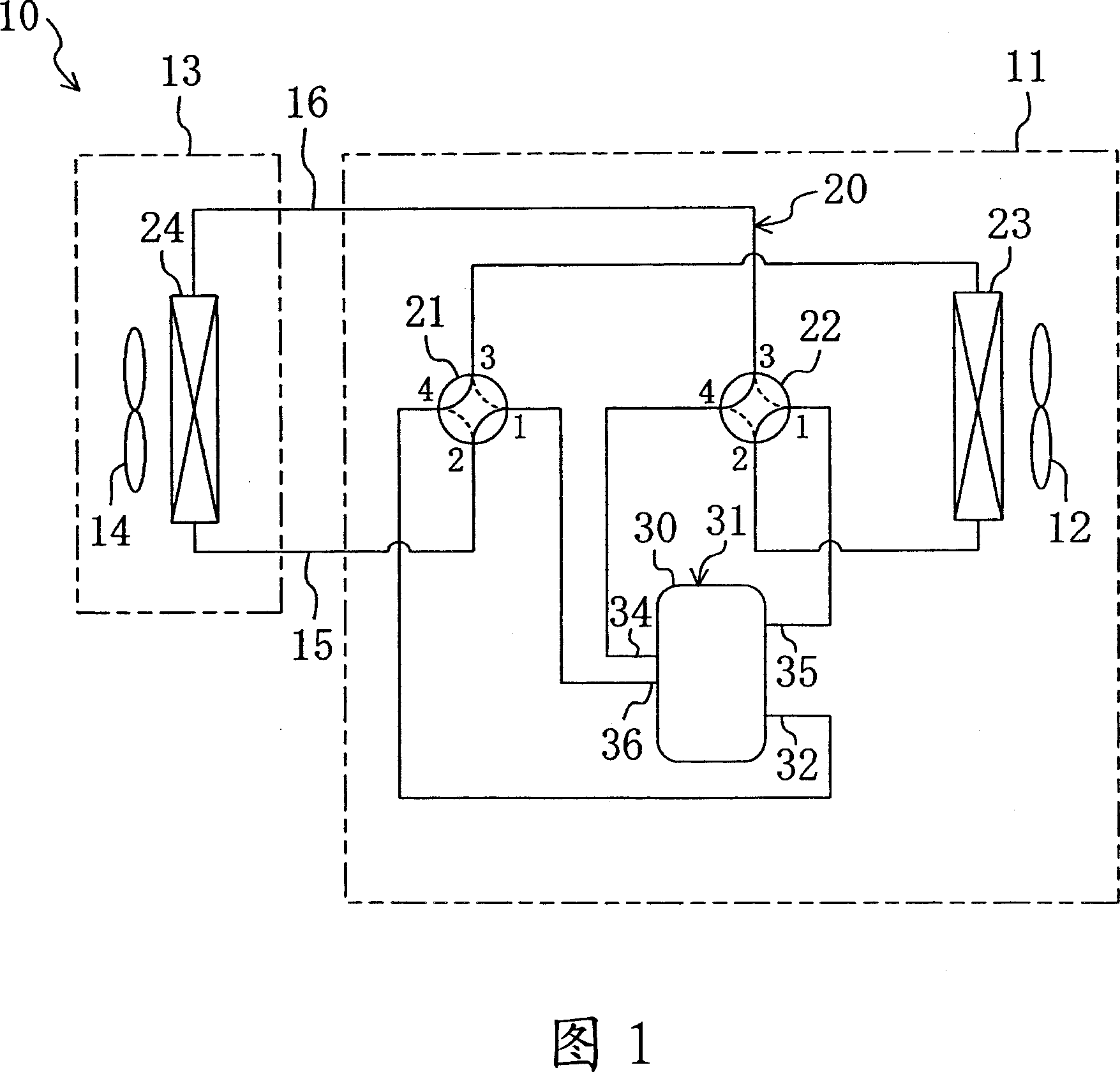
[0062] As shown in FIG. 1, the above-mentioned air conditioner 10 is of a so-called separate type, and includes an outdoor unit 11 and an indoor unit 13. The outdoor unit 11 houses an outdoor fan 12, an outdoor heat exchanger 23, a first four-way switching valve 21, a second four-way switching valve 22, and a compression / expansion unit 30. An indoor fan 14 and an indoor heat exchanger 24 are housed in the indoor unit 13. The outdoor unit 11 is installed outdoors, and the indoor unit 13 is installed indoors. In addition, the outdoor unit 11 and the indoor unit 13 are connected by a pair of connecting pipes 15 and 16. In addition, the details of the compression / expansion unit 30 will be described later.

[0063] The air conditioner 10 is provided with a refrigerant circuit 20. ...

Embodiment approach 2

[0130] The second embodiment of the present invention will be described. The present embodiment is formed by changing the structure of the compression / expansion unit 30 in the first embodiment described above. Here, regarding the compression / expansion unit 30 of the present embodiment, the difference from the above-mentioned first embodiment will be described.

[0131] As shown in FIG. 7, in the expansion mechanism 60 of the present embodiment, a center hole penetrating the rear cylinder head 62 in the thickness direction is formed in the center portion of the rear cylinder head 62. The upper end of the shaft 40 is inserted into the central hole of the rear cylinder head 62.

[0132] The upper plate 110 is provided in the expansion mechanism 60 described above. The upper plate 110 is placed on the upper surface of the rear cylinder head 62, and the center hole of the rear cylinder head 62 and the upper end surface of the shaft 40 together form an end space 95. A lead-out groove 11...

Embodiment approach 3

[0141] The third embodiment of the present invention will be described. This embodiment is formed by changing the structure of the compression / expansion unit 30 in the first embodiment described above. Here, regarding the compression / expansion unit 30 of the present embodiment, the difference from the above-mentioned first embodiment will be described.

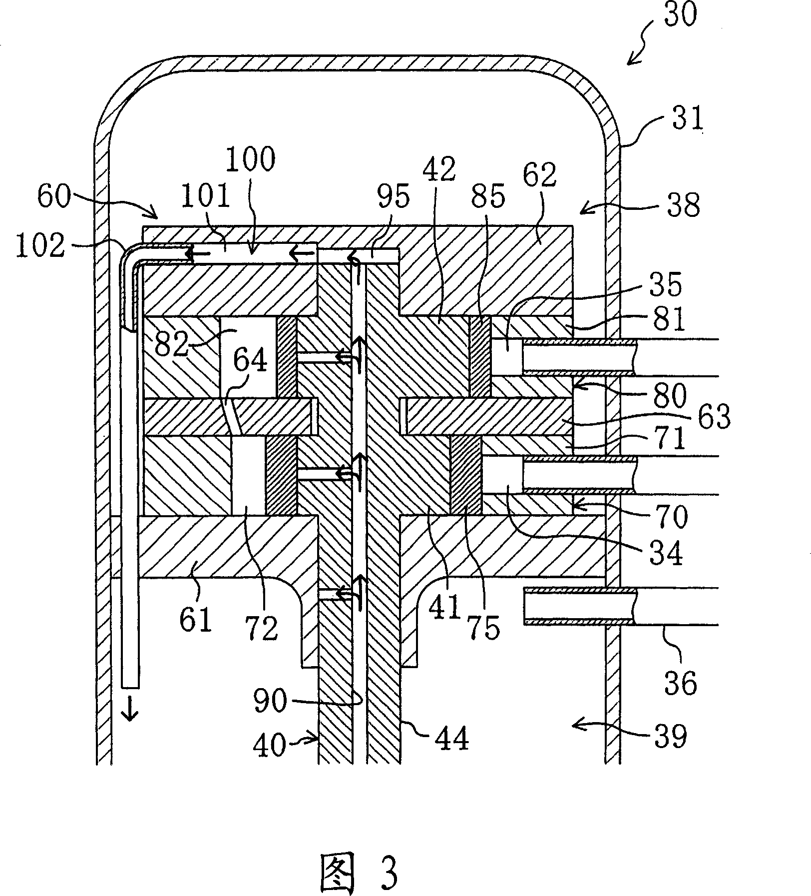
[0142] As shown in FIG. 8, in the compression / expansion unit 30 of this embodiment, an oil return passage 100 is formed in the shaft 40, and the lead-out hole 101 and the oil return pipe 102 of the rear cylinder head 62 are omitted. In the shaft 40 described above, an oil return passage 100 is formed along the oil supply passage 90.

[0143] The initial end of the oil return passage 100 is opened on the upper end surface of the shaft 40 and communicates with the end space 95. The end of the oil return passage 100 opens on the outer peripheral surface of the main shaft portion 44 of the shaft 40 and communicates with the second spa...


PUM


Abstract

In a compression / expansion unit (30) serving as a fluid machine, both a compression mechanism (50) and an expansion mechanism (60) are housed in a single casing (31). An oil supply passageway (90) is formed in a shaft (40) by which the compression mechanism (50) and the expansion mechanism (60) are coupled together. Refrigeration oil accumulated in the bottom of the casing (31) is drawn up into the oil supply passageway (90) and is supplied to the compression mechanism (50) and to the expansion mechanism (60). Surplus refrigeration oil, which is supplied to neither of the compression and expansion mechanisms (50) and (60), is discharged out of the terminating end of the oil supply passageway (90) which opens at the upper end of the shaft (40). Thereafter, the surplus refrigeration oil flows into an oil return pipe (102) from a lead-out hole (101) and is returned back towards a second space (39). This reduces the amount of heat input to the fluid flowing through the expansion mechanism from the surplus refrigeration oil which has not been utilized to lubricate the compression and expansion mechanisms.

Description

Technical field [0001] The present invention relates to an expander that generates power through expansion of a high-pressure fluid. Background technique [0002] Conventionally, there has been known a fluid machine in which an expansion mechanism, a motor, and a compression mechanism are connected with a single rotating shaft. In this fluid machine, in the expansion mechanism, power is generated by the expansion of the introduced fluid. The power generated in the expander and the power generated by the electric motor are transmitted through the rotary shaft compression mechanism. Furthermore, the compression mechanism is driven by the power transmitted from the expansion mechanism and the motor, sucking in the fluid and compressing it. [0003] Patent Document 1 discloses such a fluid machine. In FIG. 6 of this document, a fluid machine is described in which an expansion mechanism, a motor, a compression mechanism, and a rotating shaft are housed in a longitudinally long cylindr...

Claims


Application Information

Patent Timeline
Patent Type & Authority Applications(China)
IPC IPC(8): F01C1/356F01C11/00F01C13/04F01C21/04F04C18/356F04C29/02F04C23/00F04C23/02
CPCF04C23/008F04C29/023F01C1/356F01C11/00F01C13/04F04C18/356
Inventor 冈本哲也熊仓英二冈本昌和森胁道雄鉾谷克己
Owner DAIKIN IND LTD
Why Eureka
Try Eureka