Method and apparatus for infrared laser atmospheric scattering communication

An infrared laser and atmospheric scattering technology, applied in the field of optical communication, can solve the problems of no optical communication system, and achieve the effect of large working distance, high degree of commercialization, and high transmission data rate

Inactive Publication Date: 2007-03-21
SHANGHAI INST OF OPTICS & FINE MECHANICS CHINESE ACAD OF SCI
View PDF0 Cites 10 Cited by
  • Summary
  • Abstract
  • Description
  • Claims
  • Application Information

AI Technical Summary

Problems solved by technology

However, there is no such optical communication system

Method used


Image

  • Method and apparatus for infrared laser atmospheric scattering communication
  • Method and apparatus for infrared laser atmospheric scattering communication
  • Method and apparatus for infrared laser atmospheric scattering communication

Examples


Embodiment Construction

[0028] Below by embodiment the present invention will be further described, but should not limit protection scope of the present invention with this.

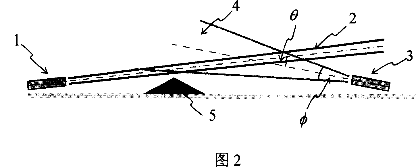
[0029] Figure 2 is a block diagram of the basic architecture of infrared laser scattering communication. In the figure: 1 is the infrared laser transmitter; 2 is the beam of the infrared laser. 3 is an infrared receiver; 4 represents the receiving aperture, which is marked as φ in the figure. 5 indicates an obstacle. θ is the angle between the axis of the receiving optical lens and the emitting laser beam. Among them, the infrared light transmitter uses a laser, which has high output power and narrow beam width, which is beneficial to increase the working distance.

[0030] The receiver optical system adopts a system with a large aperture and a large acceptance angle in order to receive as much scattered energy as possible from the infrared laser beam. Since the photons scattered from the large scattering volume go through ...


PUM


Abstract

A method for carrying out atmosphere scattering communication of infrared laser can realize nonvisual light communication through amplification shaping and electric signal processing after infrared laser emitted by light emitter and infrared laser system then modulated by signal is atmosphere-scattered and after scattered infrared laser is received by infrared waveband light detector with large receiving angle on light receiver. The device for realizing said method is also disclosed.

Description

technical field [0001] The invention is an optical communication method using an infrared laser light source as a transmitter and carrying out information transmission through atmospheric scattering. The invention belongs to the technical field of communication. Background technique [0002] Free Space Optical Communication (FSO) is an important part of the communication network system. At present, infrared laser communication has been developed relatively maturely and received great attention, including laser communication for atmospheric transmission and optical communication between satellites in outer space. These optical communication systems are realized by direct light beams, which are called Line-of-sight (LOS) communication. It is characterized by a relatively long working distance and a relatively high transmission rate. But the laser beam cannot go around obstacles, such as tall buildings, hills, islands and so on. Therefore, line-of-sight optical communicatio...

Claims


Application Information

Patent Timeline
Patent Type & Authority Applications(China)
IPC IPC(8): H04B10/10H04B10/02H04B10/11
Inventor 冯涛方祖捷陈刚熊飞
Owner SHANGHAI INST OF OPTICS & FINE MECHANICS CHINESE ACAD OF SCI
Why Eureka
Try Eureka