

Single-direction clutching mechanism
A one-way clutch and clutch technology, applied in the field of machinery, can solve problems such as high manufacturing process requirements, slippage, and failure to start the automobile engine, and achieve the effects of overcoming slippage defects, fewer components, and reasonable structural design
- Summary
- Abstract
- Description
- Claims
- Application Information
AI Technical Summary
Problems solved by technology
Method used
Image


Examples
Embodiment 1
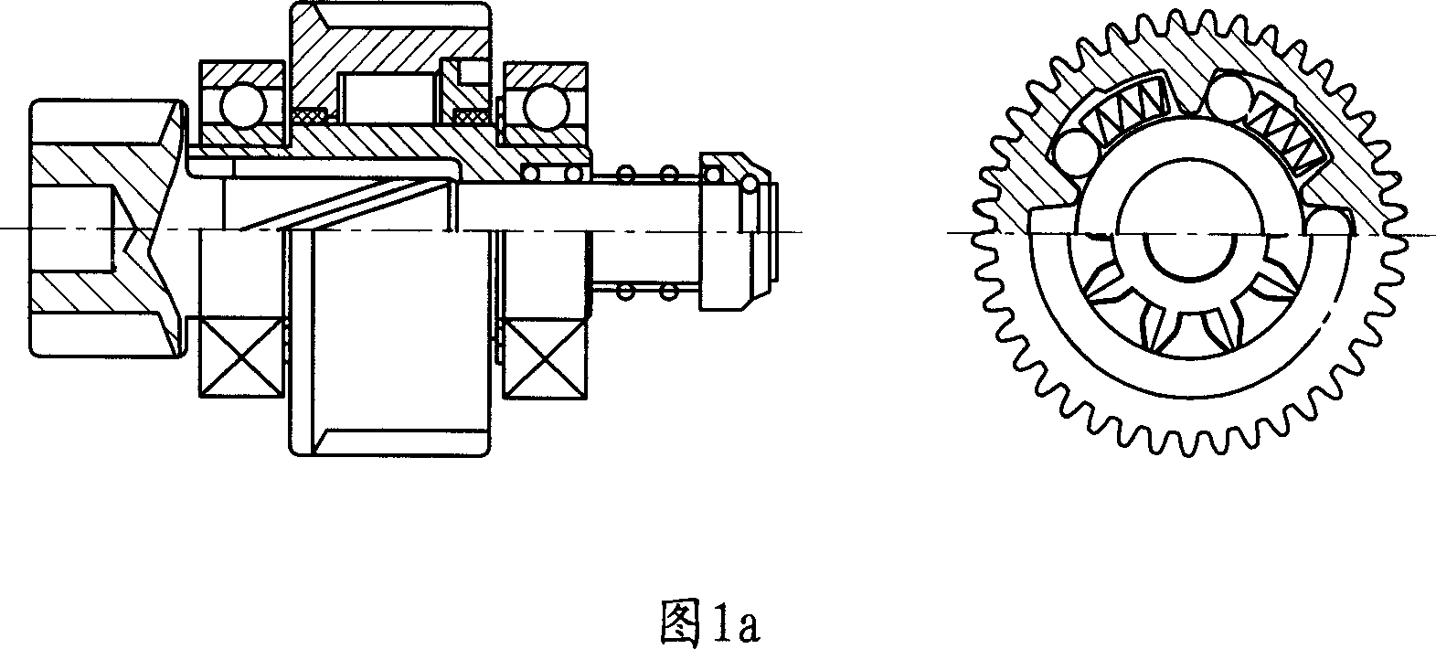
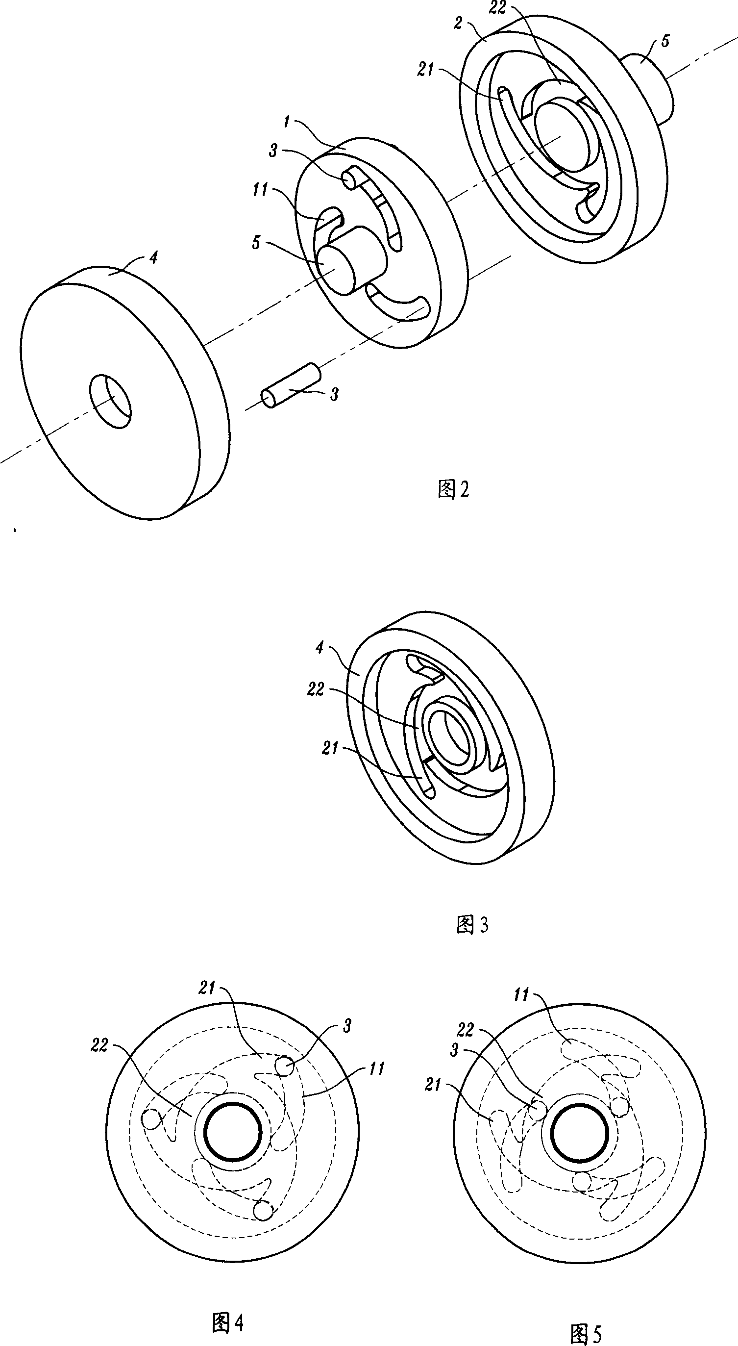
[0022] Referring to Fig. 2, Fig. 3, Fig. 4 and Fig. 5, this is an example of a rotating body forming a disk-like matching structure. The end surface of the first rotating body 1 is provided with more than two guide grooves, generally three to five are preferred. The guide groove is a through groove 11, and the second rotating body 2 is provided with more than two guide grooves having a certain angle with the through groove 11 toward the end surface of the first rotating body 1. The guide grooves are blind grooves 21, and more than two blind grooves Groove 21 connects into an annular cavity 22 near the central end of the axis, and the sliding body is a cylinder 3, which is placed in the through groove 11 of the first rotating body, and its double ends can be inserted into the blind groove 21 of the second rotating body and end cover 4 or In the annular cavity 22, the cavity width of the annular cavity 22 is equivalent to the diameter of the sliding body of the cylinder 3, and th...
Embodiment 2
[0026] With reference to Fig. 6, the rotating body of this example forms the circumferential surface matching structure, and the surface of the first rotating body 1 has a semicircular guide groove 6, and the second rotating body 2 is provided with the clutch inner and outer cavities 23, 24 of the coaxial center line, and the clutch The inner cavity 23 matches the diameter of the first rotating body 1, and is sleeved on the first rotating body to form a dynamic fit. The projection angle) of the semicircular guide groove 6, the sliding body is a ball 31, which can be movably placed in the intersecting cavity of the first rotating body 1 and the second rotating body 2 semicircular guide groove 6, the clutch outer cavity of the second rotating body 2 24 forms a cavity in which the ball 31 can move freely, that is, once the ball 31 slides into the clutch outer cavity 24, the two rotating bodies will lose the meshing state, and the diameter of the clutch outer cavity 24 is at least ...
PUM
 Abstract
Description
Claims
Application Information