

Calcinated ceramic-trick roller-bed kiln
A technology of porcelain brick and roller kiln, which is applied in the direction of furnace type, furnace, lighting and heating equipment, etc., can solve the problems that the cross section temperature difference of roller kiln can not be effectively eliminated, the resistance of flue gas flow is small, etc., and achieve Simple structure, improved product quality and production efficiency, and convenient adjustment
- Summary
- Abstract
- Description
- Claims
- Application Information
AI Technical Summary
Problems solved by technology
Method used
Image

Examples
no. 1 example
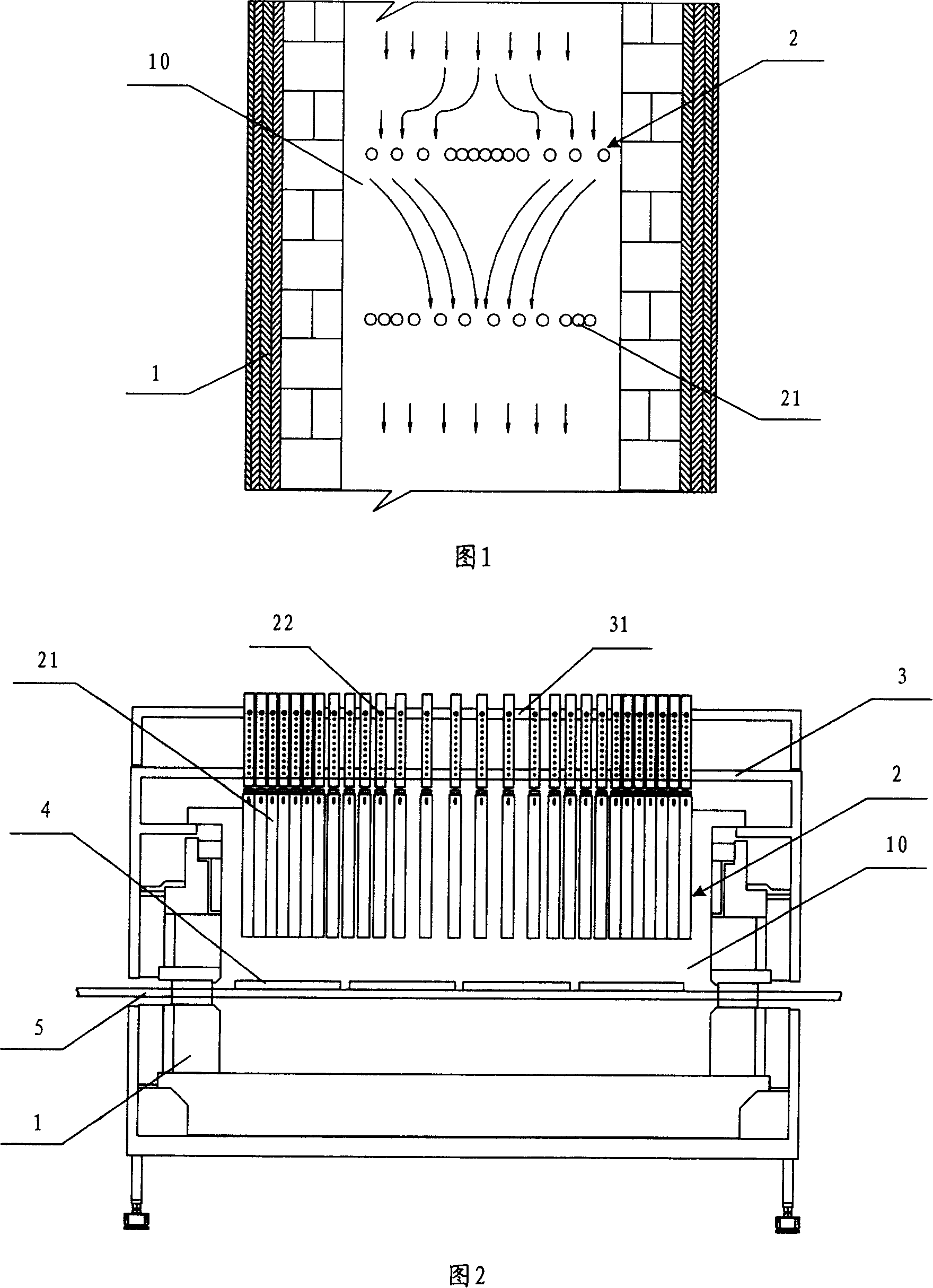
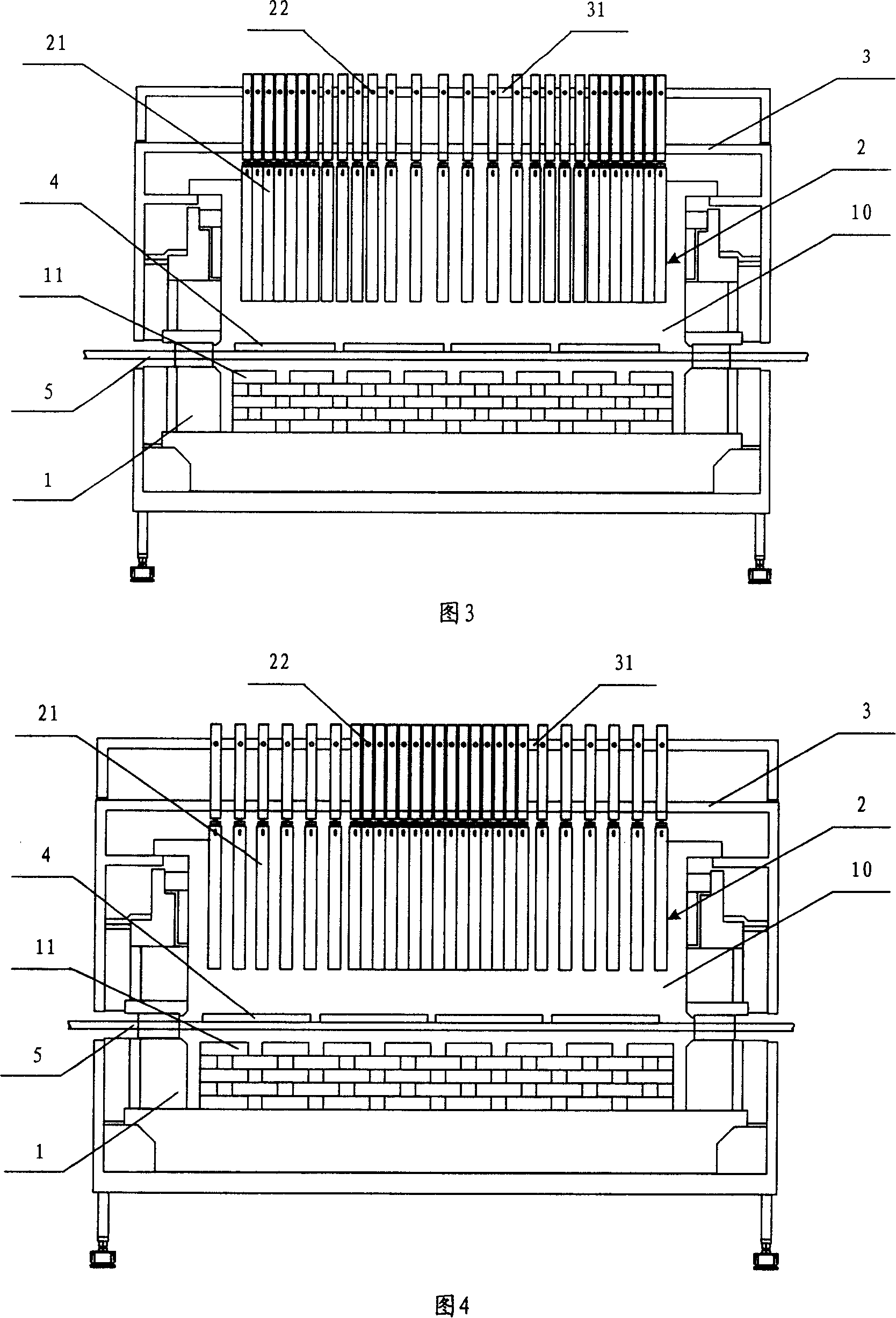
[0030] Fig. 3 is a schematic structural view of the first embodiment of the present invention, in which the gratings are arranged in a set spacing manner with sparse middle and denser sides in the kiln channel. As shown in Figure 3, a bracket 3 is provided on the kiln body 1 of this embodiment, a guide groove 31 is provided on the bracket 3, a guide hole 22 is opened on the grid bar 21, and the bolt passes through the guide hole 22 and the guide groove 31 to connect the grid The bars 21 are connected to the support 3, and the distance between the grid bars 21 can be adjusted due to the guide grooves 31, so that the grid bars 21 are suspended in the kiln channel 10 in a manner that is sparse in the middle and dense on both sides. In the upper part, by concentrating the airflow in the kiln passage to the middle area, the purpose of increasing the middle temperature is achieved, and the temperature of the cross-section of the kiln passage is evenly distributed when the middle temp...
no. 2 example
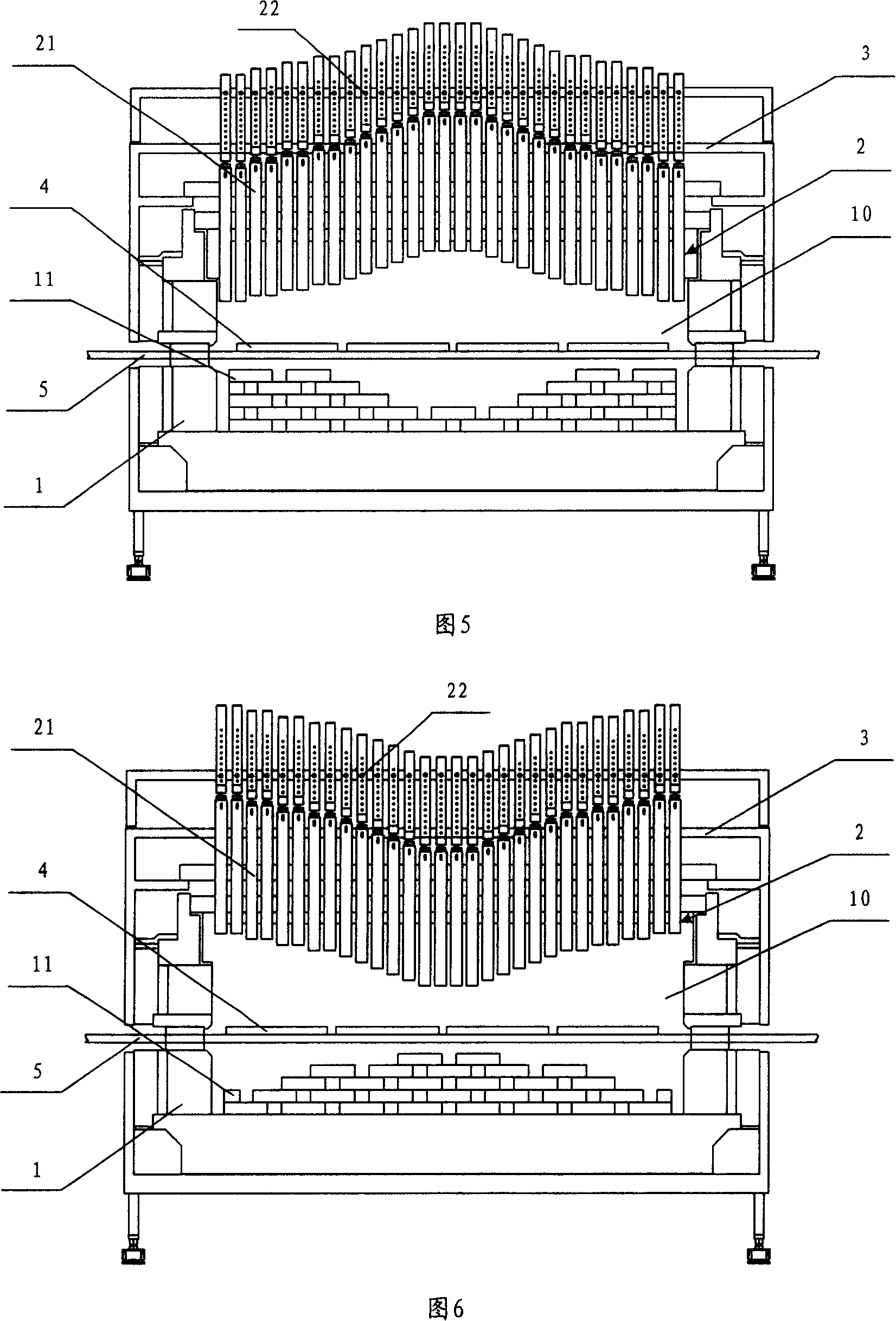
[0034] Fig. 4 is a schematic structural diagram of the second embodiment of the present invention, in which the grid bars are arranged in a set spacing manner with dense middle and sparse sides in the kiln channel. As shown in Figure 4, a bracket 3 is provided on the kiln body 1 of this embodiment, a guide groove 31 is provided on the bracket 3, a guide hole 22 is opened on the grid bar 21, and the bolt passes through the guide hole 22 and the guide groove 31 to connect the grid. The bars 21 are connected on the support 3, and the distance between the grid bars 21 can be adjusted due to the guide grooves 31, so that the grid bars 21 are suspended in the kiln channel 10 in a manner that is dense in the middle and sparse on both sides. In the upper part, by expanding the airflow in the kiln channel to the two sides, the purpose of increasing the temperature on both sides is achieved, and the temperature of the cross-section of the kiln channel is evenly distributed when the tempe...
no. 3 example
[0037] Fig. 5 is a schematic structural view of the third embodiment of the present invention, in which the grid bars are arranged in the way of setting the extension length in the middle of the kiln passage and lower on both sides. As shown in Figure 5, the kiln main body 1 of this embodiment is provided with a bracket 3, and several guide holes 22 are provided on the grid bar 21, and the bolt passes through one of the guide holes 22 to connect the grid bar 21 to the bracket 3, due to the guide The holes 22 can adjust the length of each grid bar 21 extending into the kiln channel, so that the grid bar 21 is suspended on the upper part of the kiln channel 10 in the kiln channel 10 in a manner that the middle is high and both sides are low. The internal air flow is concentrated to the middle area to achieve the purpose of increasing the middle temperature, so that the cross-section temperature of the kiln channel is evenly distributed when the middle temperature is low.
[0038...
PUM
 Abstract
Description
Claims
Application Information