

Perpendicular magnetization magnetic element utilizing spin transfer
一种磁性元件、磁性的技术,应用在磁性存储系统领域,能够解决切换电流高等问题
- Summary
- Abstract
- Description
- Claims
- Application Information
AI Technical Summary
Problems solved by technology
Method used
Image

Examples
Embodiment Construction
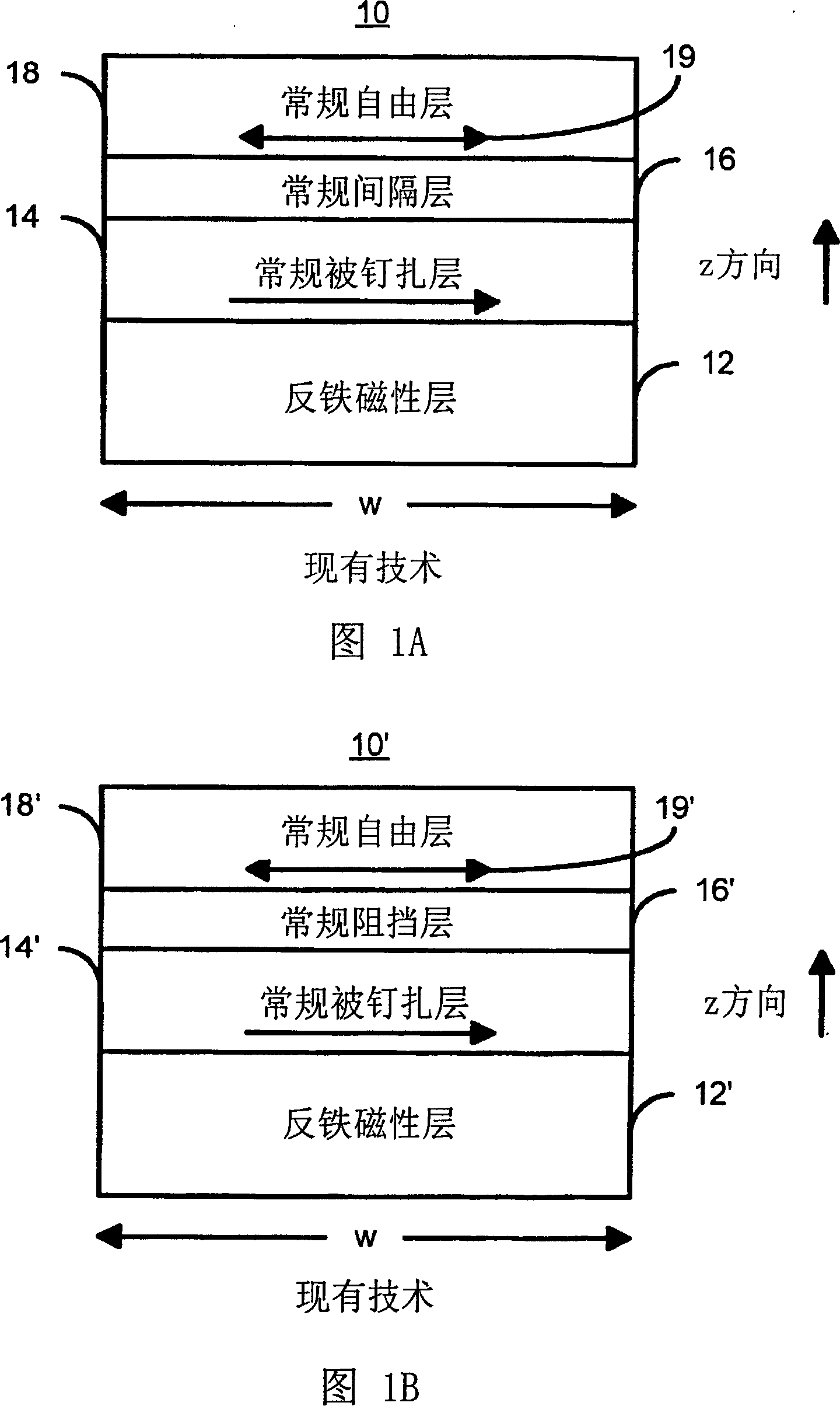
[0031] The present invention relates to improvements in magnetic elements such as MRAMs and magnetic memories. The following description enables one of ordinary skill in the art to make and use the invention, and is provided in the context of a patent application and its requirements. Various modifications to the preferred embodiment will be readily apparent to those skilled in the art, and the general principles herein can be applied to other embodiments. Thus, the present invention is not intended to be limited to the embodiments shown but is to be accorded the widest scope consistent with the principles and features described herein.
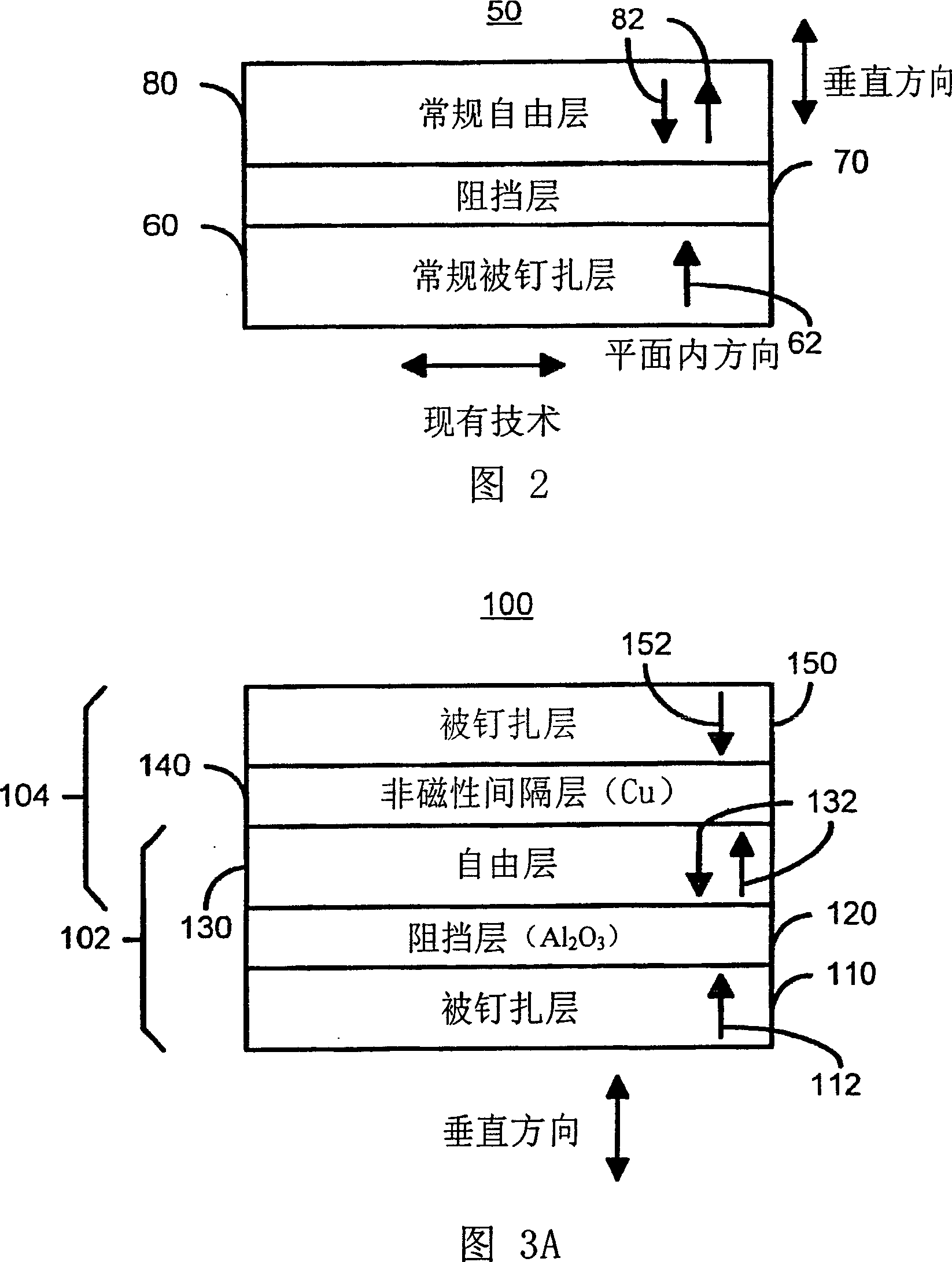
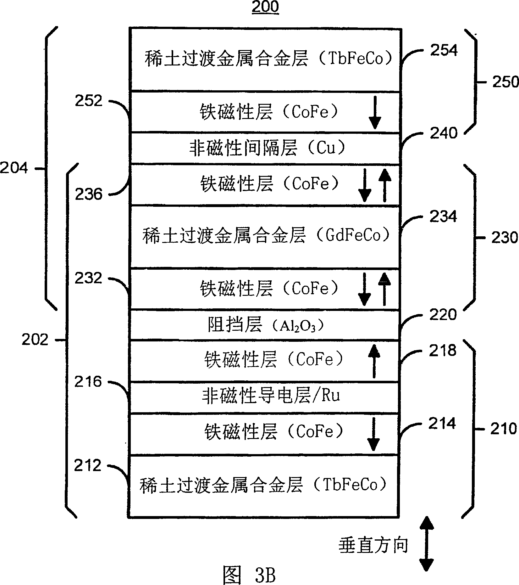
[0032] The present invention proposes a method and system for providing a magnetic element usable in a magnetic memory. The method and system include providing a first pinned layer, an insulating barrier layer, a free layer, a conductive non-magnetic spacer layer, and a second pinned layer. Each pinned layer has a pinned layer easy axis. A...
PUM
 Abstract
Description
Claims
Application Information