Stitching apparatus

A technology of a binding clip and a linkage device is applied in the direction of binding, etc., which can solve the problems of the thickness of the binding device and the product, which are troublesome and susceptible to interference, and achieve the effect of reducing the susceptibility to interference.

Inactive Publication Date: 2007-04-04
MULLER MARTINI HLDG
View PDF3 Cites 7 Cited by
  • Summary
  • Abstract
  • Description
  • Claims
  • Application Information

AI Technical Summary

Problems solved by technology

[0007] However, in all the devices described in the prior art, the adaptation of the binding device to the product thickness is complex and easily disturbed

Method used


Image

  • Stitching apparatus
  • Stitching apparatus

Examples


Embodiment Construction

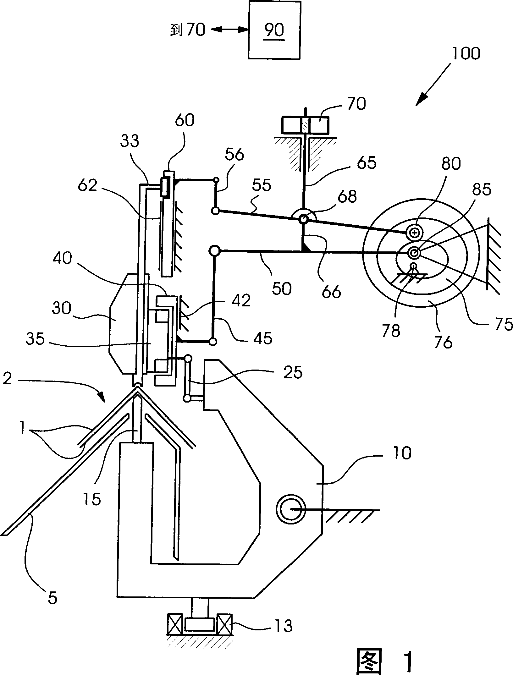
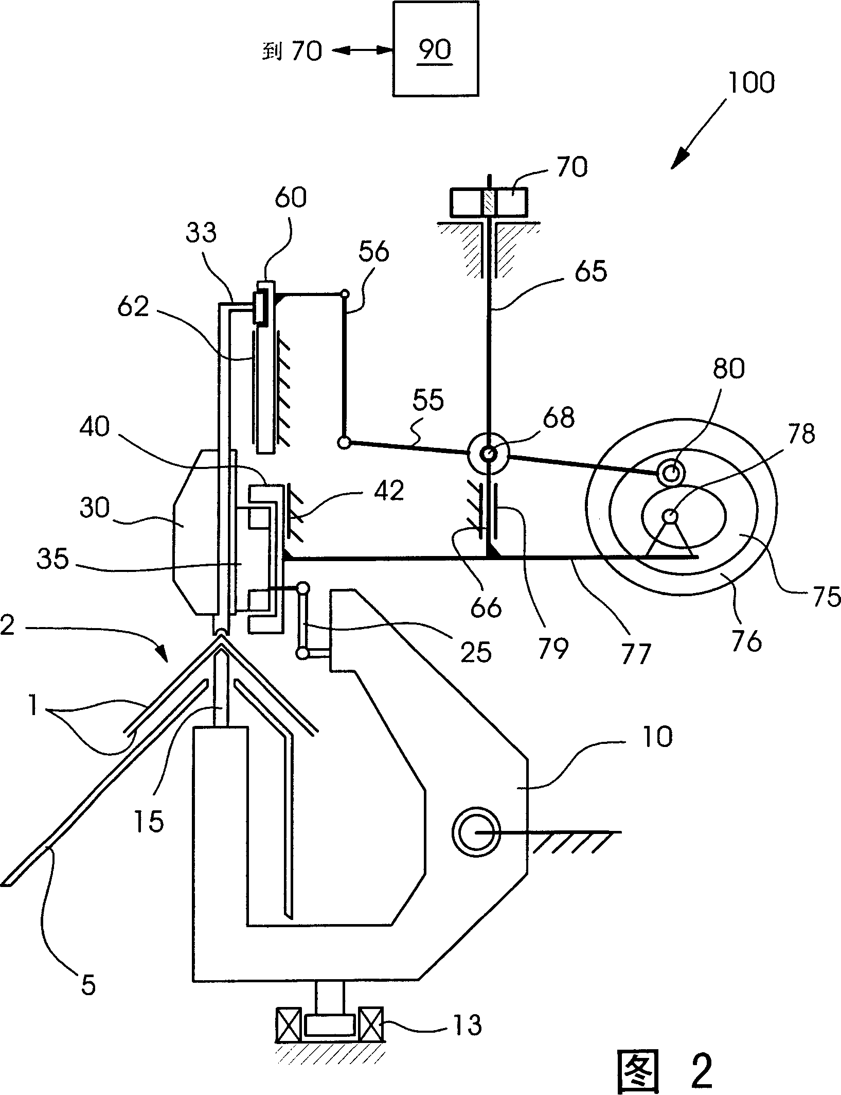
[0021] The embodiment of the binding device 100 according to the invention shown in FIGS. 1 and 2 is limited to describing and illustrating the essential details of the invention. Other units which are necessary for the operation of the bookbinding device, in particular also do not differ from the background art or are borrowed from the background art, such as guides, control devices, drives, fastening mechanisms, etc., are not further described and / or are given for the sake of clarity neglect. In particular only one slide 33 is shown for controlling the movement process in the stitching head, although typically a pusher slide and a bender slide are used for this.

[0022] The individual signatures 1 are collected in a known manner in a saddle-shaped stack 2 on a book collection chain (not shown, but known to the skilled person from the above-mentioned background art) and conveyed to a binding device 100 , are stapled there and then trimmed on three open sides. The stack of ...


PUM


Abstract

The present invention relates to a stitching apparatus 100 for manufacturing printed products, in particular in a gathering and stitching linkage machine. The stitching apparatus 100 comprises a stitching sliding carriage 10, at least one stitching head 30 for shaping and driving a staple into a stack 2 of signatures 1, and at least one clinch box 15 for closing the staple driven through the signatures 1, wherein the stitching apparatus 100 comprises adjusting device 45, 50, 55, 56, 65, 66, 70, 77 for vertically moving the stitching head 30 to allow the stitching apparatus 100 to adapted to the thickness of the stack 2 of signatures 1.

Description

technical field [0001] The invention relates to a bookbinding device for producing printed products, in particular in a collating linkage. Background technique [0002] The device for binding the folded signatures or printed products is typically provided in a so-called collator or collator. Such a collating and binding linkage is known, which distributes the folded printed products, places them on a conveyor, such as a conveyor chain or similar, collects and collates them, and then feeds them To a stapling station, if necessary then to a post-processing unit, such as an edge trimmer, a stacker or the like. [0003] For example, document EP 0 916 514 A1 discloses a typical collating linkage with a front and a rear book chain as a transport device. The individual folded sheets or folded signatures are separated from the stack by the folded sheet feeder, opened and placed on the collection chain. Guide strips are arranged between the book collection chains, the upper sectio...

Claims


Application Information

Patent Timeline
IPC IPC(8): B42B4/00
CPCB42B4/00
Inventor 托尔斯滕·布吕纳西格马尔·蒂舍尔
Owner MULLER MARTINI HLDG
Why Eureka
Try Eureka