eeprom power supply circuit and eeprom
A power supply circuit and internal circuit technology, applied in information storage, static memory, instruments, etc., can solve the problems of EEPROM working state interference, long power line, etc., to achieve the effect of reducing interference and facilitating wiring
Active Publication Date: 2020-12-25
SHANGHAI BEILING
View PDF5 Cites 0 Cited by
- Summary
- Abstract
- Description
- Claims
- Application Information
AI Technical Summary
Problems solved by technology
However, due to the actual operation process, the power line connected to the EEPROM is often long, which is easy to interfere with the working state of the EEPROM
Method used
View moreImage
Smart ImageViewing Examples
Examples
Embodiment 2
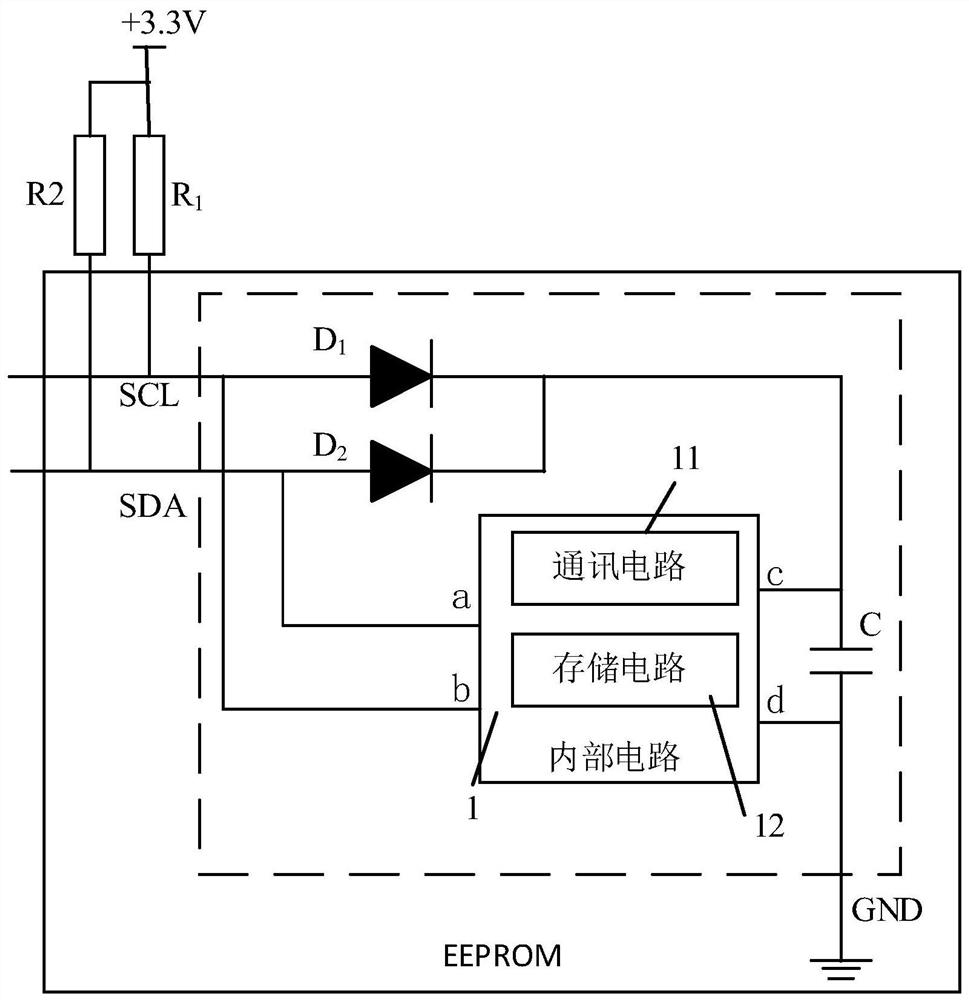
[0036] Such as image 3 As shown, this embodiment also provides an EEPROM, and the EEPROM includes the above-mentioned power supply circuit of the EEPROM.
Login to View More PUM
 Abstract
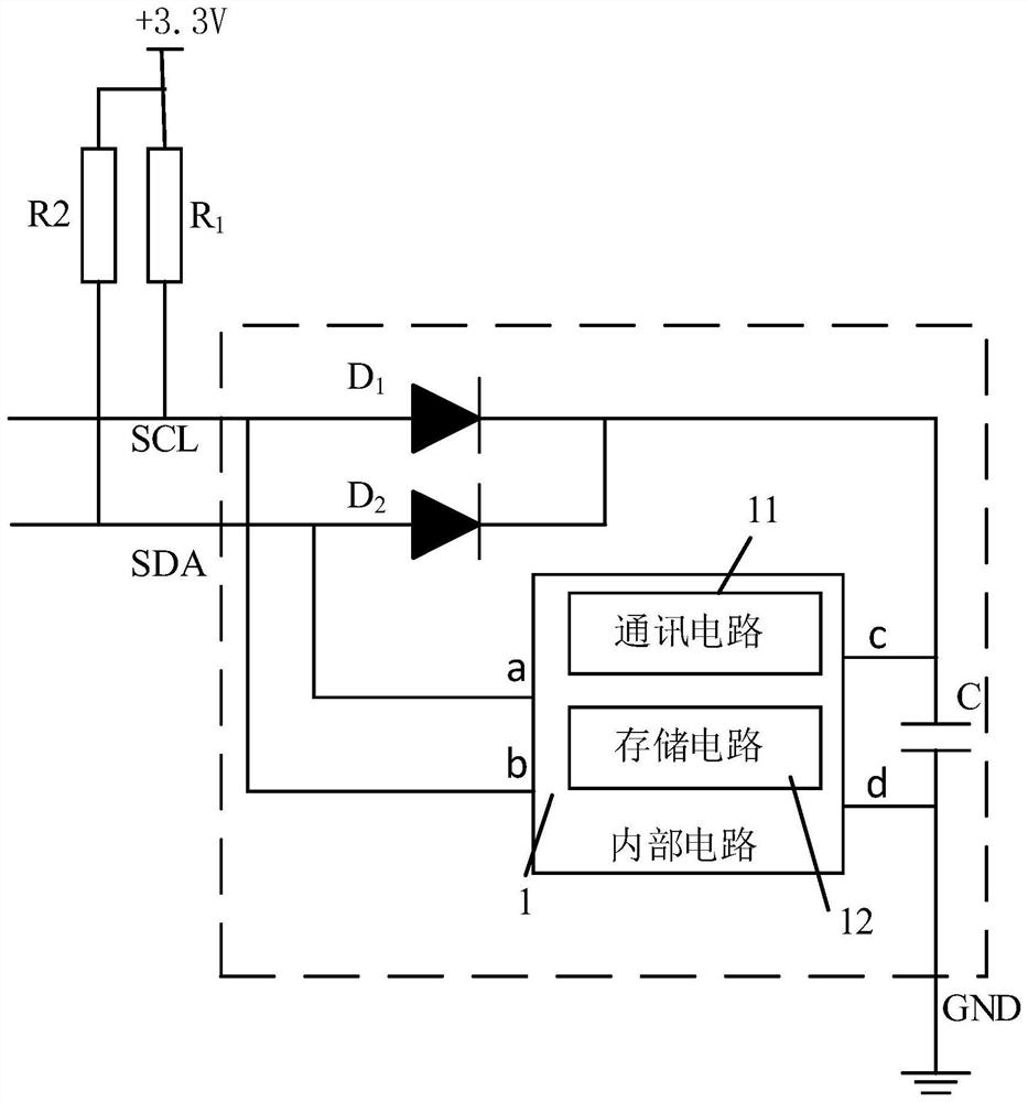
The invention discloses a power supply circuit of an EEPROM (electrically erasable programmable read and write memory) and the EEPROM. The EEPROM comprises a clock signal pin, a data signal pin and aground pin, and the power supply circuit comprises a first diode and a capacitor, wherein the clock signal pin is electrically connected with a positive electrode of the first diode and a clock signalinput end of an internal circuit; the data signal pin is electrically connected with a data signal input end of the internal circuit; one end of the capacitor is electrically connected with a negative electrode of the first diode and a power input end of the internal circuit, and the other end of the capacitor is electrically connected with the ground pin and a power output end of the internal circuit. The power supply circuit of the EEPROM and the EEPROM have the advantages that a working power supply is provided for the internal circuit of the EEPROM under the condition that one power supply line is omitted, and accordingly, the risk that the power supply line is easy to interfere due to being too long is avoided, and wiring is facilitated for a user.
Description
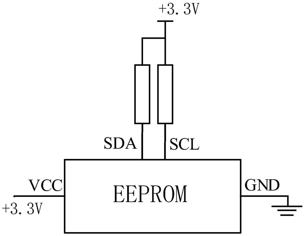
technical field [0001] The invention relates to the technical field of integrated circuits, in particular to an EEPROM (Electrically Erasable Programmable Read and-Write Memory, Electrically Erasable Read-Only Memory) power supply circuit and the EEPROM. Background technique [0002] Such as figure 1 As shown, the existing EEPROM includes a total of four power supply lines and IIC (Inter-Integrated Circuit, integrated circuit bus) communication lines. Wherein, the power supply line includes a power line and a ground line, the power line is electrically connected to the voltage input pin VCC of the EEPROM, provides a DC voltage of 3.3V to the EEPROM through the power line, and the ground line is connected to the ground pin GND of the EEPROM. The communication line includes a clock signal input line and a data signal input line, the clock signal input line is electrically connected to the clock signal pin SCL of the EEPROM, the data signal input line is electrically connected...
Claims
Login to View More Application Information
Patent Timeline
 Patent Type & Authority Patents(China)
IPC IPC(8): G11C16/30
Inventor 姜婷沈韶清张文骐丁迪路静朱小红龚庆
Owner SHANGHAI BEILING
Features
- R&D
- Intellectual Property
- Life Sciences
- Materials
- Tech Scout
- Unparalleled Data Quality
- Higher Quality Content
- 60% Fewer Hallucinations
Learn More Browse by: Latest US Patents, China's latest patents, Technical Efficacy Thesaurus, Application Domain, Technology Topic, Popular Technical Reports.
© 2025 PatSnap. All rights reserved.Legal|Privacy policy|Modern Slavery Act Transparency Statement|Sitemap|About US| Contact US: help@patsnap.com


