Scanning system and transmitting and receiving device for a scanning system

A scanning system and scanning equipment technology, which is applied in the field of scanning systems, can solve problems such as signal loss, the influence of scanning system range, beam deflection, etc., and achieve the effect of reducing the diameter of the beam

Pending Publication Date: 2020-05-01
ROBERT BOSCH GMBH
View PDF12 Cites 0 Cited by
  • Summary
  • Abstract
  • Description
  • Claims
  • Application Information

AI Technical Summary

Problems solved by technology

[0005] If the diameter of the rotating element is chosen too small, this can in some cases result in signal loss and incomplete beam deflection
This will also negatively affect the range of the scanning system

Method used


Image

  • Scanning system and transmitting and receiving device for a scanning system
  • Scanning system and transmitting and receiving device for a scanning system
  • Scanning system and transmitting and receiving device for a scanning system

Examples


Embodiment Construction

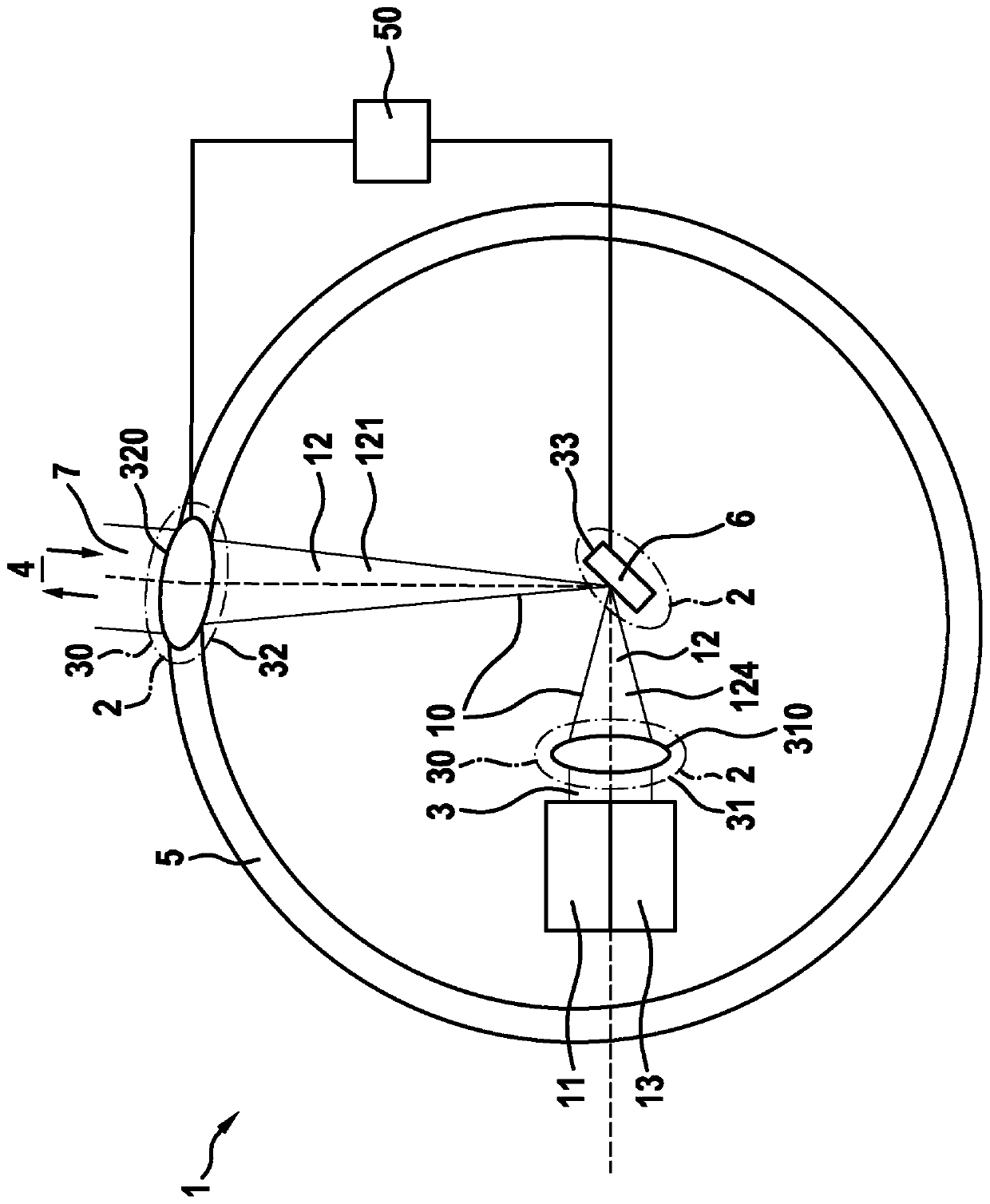
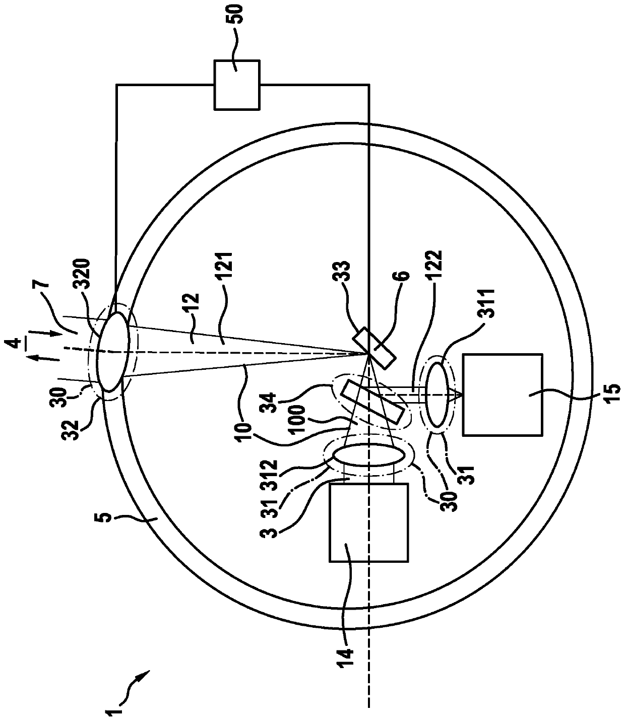
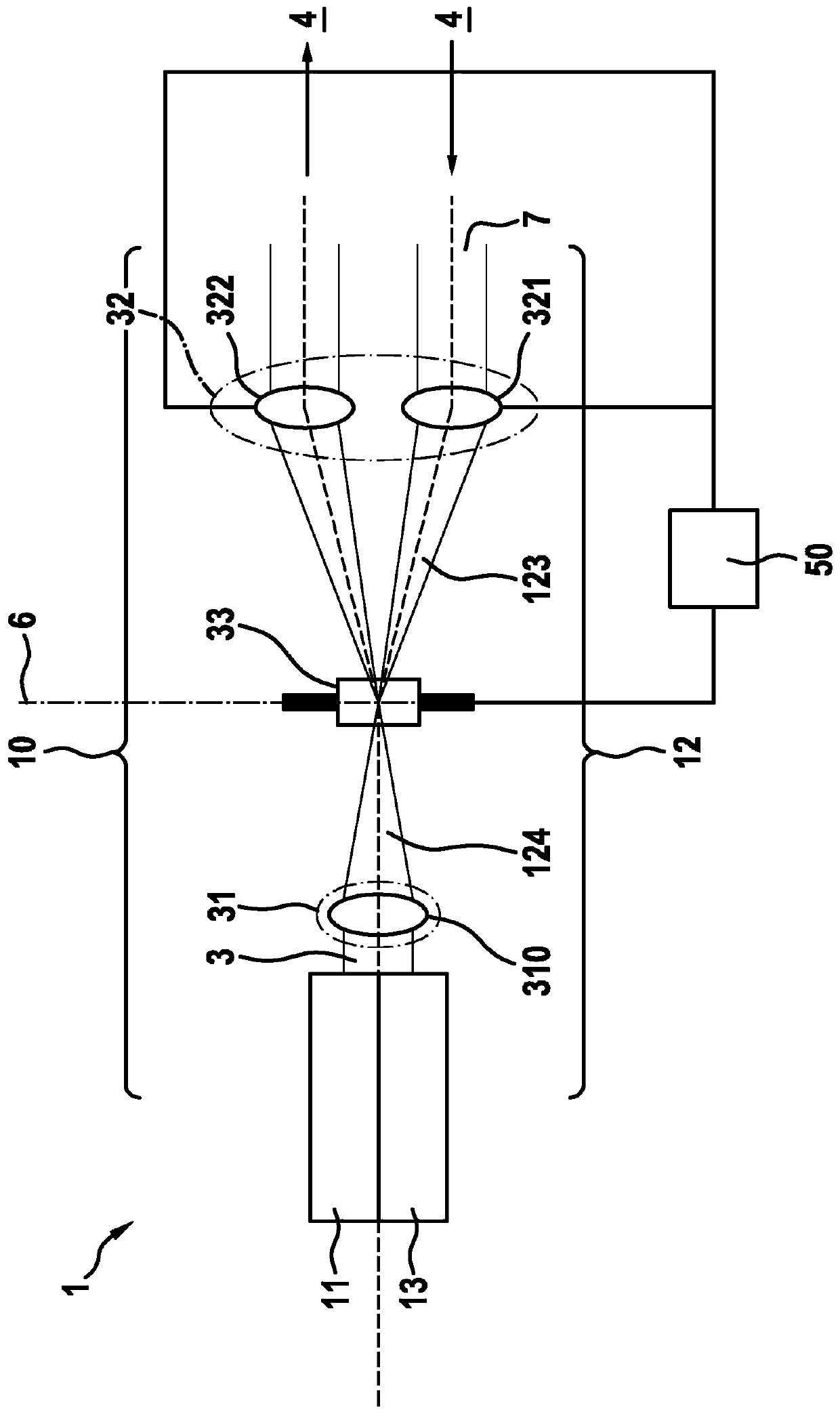
[0030] Embodiments of scanning systems that may be used to scan 3D geometries are described with reference to the following figures. The design of the system described here can be used, for example, in automotive lidar systems or building scanning systems. Such systems are based on sending a light beam for scanning a target object and from which the light beam is reflected back to the receiver. Furthermore, the distance of the target object in the observation area can be ascertained from the signal propagation time and the speed of light.

[0031] figure 1 A first embodiment of the scanning system 1 is shown in . The scanning system 1 comprises a transmitter 11 , a receiver 13 and a rotating scanning device 2 . The rotating scanning device 2 has an optics 30 and a rotating deflection unit 33 . Furthermore, the optics 30 comprise a first focusing device 31 with a first converging lens 310 and a rotating second focusing device 32 with a first converging lens 320 . The rotat...


PUM


Abstract

The invention relates to a scanning system (1), having a transmitting path (10), a receiving path (12), a transmitter (11), a receiver (13) and a rotating scanning device (2). The transmitter (11) emits radiation (3), which propagates along an optical axis on the transmitting path (10). The radiation (7) received from the target object (4) is detected by the receiver (13) on the receiving path (12). Furthermore, the rotating scanning device (2) comprises an optical unit (30) and a rotating deflecting unit (33), which deflects the radiation of the transmitting path (10) and of the receiving path (12). The optical unit (30) has a first focusing apparatus (31) and a rotating second focusing apparatus (32). The movements of the rotating deflecting unit (33) and of the rotating second focusingapparatus (32) occur synchronously in order to ensure alignment of the deflected radiation with the second focusing apparatus (32). Furthermore, the first focusing apparatus (31) images the radiation(3) emitted by the transmitter (11) onto the rotating deflecting unit (33) in such a way that the beam diameter at the rotating deflecting unit (33) is reduced. In addition, the rotating deflecting unit (33) deflects the radiation (3) onto the rotating second focusing apparatus (32), and the rotating second focusing apparatus (32) collimates the radiation (3) toward the target object (4). The rotating second focusing apparatus (32) images the radiation (7) received from the target object (4) onto the rotating deflecting unit (33) in such a way that the beam diameter at the rotating deflectingunit (33) is reduced, and the rotating deflecting unit (33) deflects the received radiation (7) to the receiver (13).

Description

technical field [0001] The invention relates to a scanning system comprising transmit and receive paths, a transmitter, a receiver and a rotating scanning device. The invention also relates to a sending device and a receiving device for such a scanning system. Background technique [0002] Scanning systems are known from the prior art which can be used, for example, in automotive lidar systems, building scanning systems or for detecting 3D geometries. The scanning system is based on the fact that a light beam is sent for scanning a target object and the light beam is reflected from the target object back to the receiver. From the signal propagation time and the speed of light, for example, the distance of a target object in the observation range can be ascertained. [0003] Scanning systems can be realized on the basis of various principles and in particular with the aid of movable components. In the embodiment of the scanning system, the distinguishing criterion is wheth...

Claims


Application Information

Patent Timeline
Patent Type & Authority Applications(China)
IPC IPC(8): G01S7/481G01S17/42G01S17/89G01S17/931
CPCG01S17/42G01S17/89G01S7/4812G01S7/4817G01S17/931
Inventor A·霍莱切克M·哈塔斯R·哈斯B·施密特
Owner ROBERT BOSCH GMBH
Why Eureka
Try Eureka