High-speed sheet feeding without grip pliers

A plate-shaped, flat-plate technology, applied in the field of feeding devices, can solve problems such as increasing safety, and achieve the effects of eliminating unevenness, improving susceptibility to interference, and reducing time

Inactive Publication Date: 2007-02-07
EMCO GMBH
View PDF1 Cites 0 Cited by
  • Summary
  • Abstract
  • Description
  • Claims
  • Application Information

AI Technical Summary

Problems solved by technology

If this strip area (often also referred to as gripper trim) is minimized, then when the last row of wafers is stamped, if the gripper then extends into the tool area and in this case very close to the stamping head or Punch, with increased safety concerns

Method used


Image

  • High-speed sheet feeding without grip pliers
  • High-speed sheet feeding without grip pliers
  • High-speed sheet feeding without grip pliers

Examples


Embodiment Construction

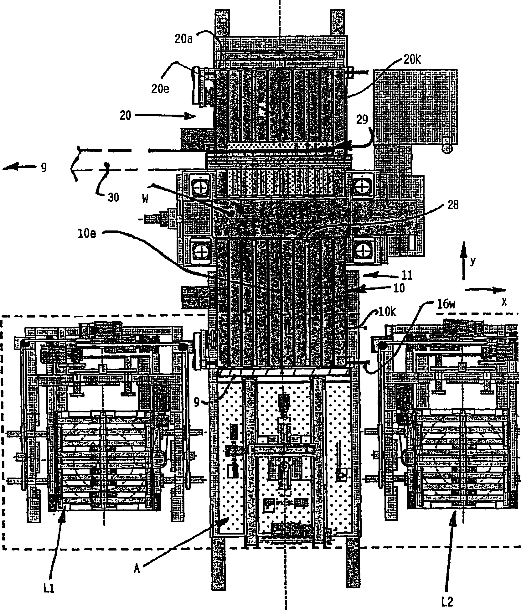
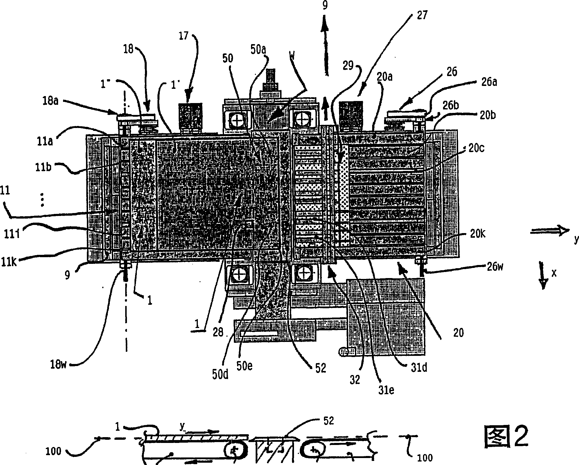
[0046] according to figure 1 The first embodiment represents the assembled state of the parts used. An upper feed device 10 and a similar lower feed device 11 (not visible) each consist of a plurality of parallel endless belts, in this example 10 belts 10 a to 10 k arranged next to one another. The middle band 10e is symbolically marked. The conveying device is oriented on a working area W, which in this example is formed by a transversely extending punching device 50 . Behind the tool there is a feeding device 20 which is designed similarly to the feeding device 10 . Its internal conveyor is partially covered by a discharge system 29 . In this example, too, ten conveyor belts are arranged closely next to each other as circulation systems, denoted by 20a to 20k. Also shown here is a symbolic conveyor belt 20e, which is a continuation of the input conveyor belt 10e.

[0047] The input conveyors 10 , 11 as first plate infeed and the outfeed conveyor 20 as second plate infee...


PUM

PropertyMeasurementUnit
thicknessaaaaaaaaaa

Abstract

The invention concerns a conveying device for sheet steel plates and for moving several sheets (1, 1') inside or through a working zone (W; 50) wherein the sheets are machined. The inventive feeding device comprises first and second sheet feeders (10, 11; 20) which feed the sheets in controlled manner to the working zone (W) so that the sheets are machined with positional accuracy. The first sheet feeder (10, 11) is located on an input side of the tool zone and the second sheet feeder (20) is located on an output side of the tool zone. The two sheet feeders (10, 20; 11; 20) are mutually synchronized in their movements (x, y) when feeding forward the sheet (1), the sheet driven by the synchronous movement being maintained by the two sheet feeders. The invention provides the advantages of increased speed and safety. It is possible to increase the speed without the sheet being deformed or losing its flatness.

Description

[0001] This case is a divisional application of a patent application with an application date of October 28, 2002, an application number of 02821927.9, and an invention title of "High-speed Board Transmission Without Clamps". technical field [0002] The invention relates to a feed device and an associated method for conveying a plate-like plate, commonly called a plate, to a work area where the plate is processed. The processing may include a stamping step in which discs are punched out of the plate, the discs being arranged closely spaced on the plate by the remaining residual grid. The invention also relates to a belt drive in which the circulating belt takes over the conveying function of the plates. Background technique [0003] The starting point is the feed device of the prior art, wherein the plate edge facing away from the tool area is gripped with clamps at the rear end, so that the plate is transported to the tool area on a non-moving infeed table and is used here...

Claims


Application Information

Patent Timeline
Patent Type & Authority Applications(China)
IPC IPC(8): B21D43/02B21D28/06B21D43/12B21D43/18B65G15/58B21D43/11
CPCB21D43/11B21D43/026Y10T83/6582
Inventor 格尔德·冯·阿尔沃登
Owner EMCO GMBH
Why Eureka
Try Eureka