Refrigerant compressor and refrigerant cycle device including the same

A refrigerant cycle and refrigerant technology, applied to compressors, refrigerators, compressors, etc., to achieve the effect of improving reliability and performance

Inactive Publication Date: 2007-04-04
SANYO ELECTRIC CO LTD
View PDF1 Cites 1 Cited by
  • Summary
  • Abstract
  • Description
  • Claims
  • Application Information

AI Technical Summary

Problems solved by technology

[0009] The present invention is made to solve such problems of the prior art, and the purpose is to provide a kind of unfavorable phenomenon that can eliminate the oil flowing into the outside of the refrigerant compressor when sealing the oil , and suppress the amount of oil seal as much as possible, and ensure a sufficient amount of oil in the refrigerant compressor and the refrigerant cycle device equipped with the refrigerant compressor

Method used


Image

  • Refrigerant compressor and refrigerant cycle device including the same
  • Refrigerant compressor and refrigerant cycle device including the same

Examples


Embodiment Construction

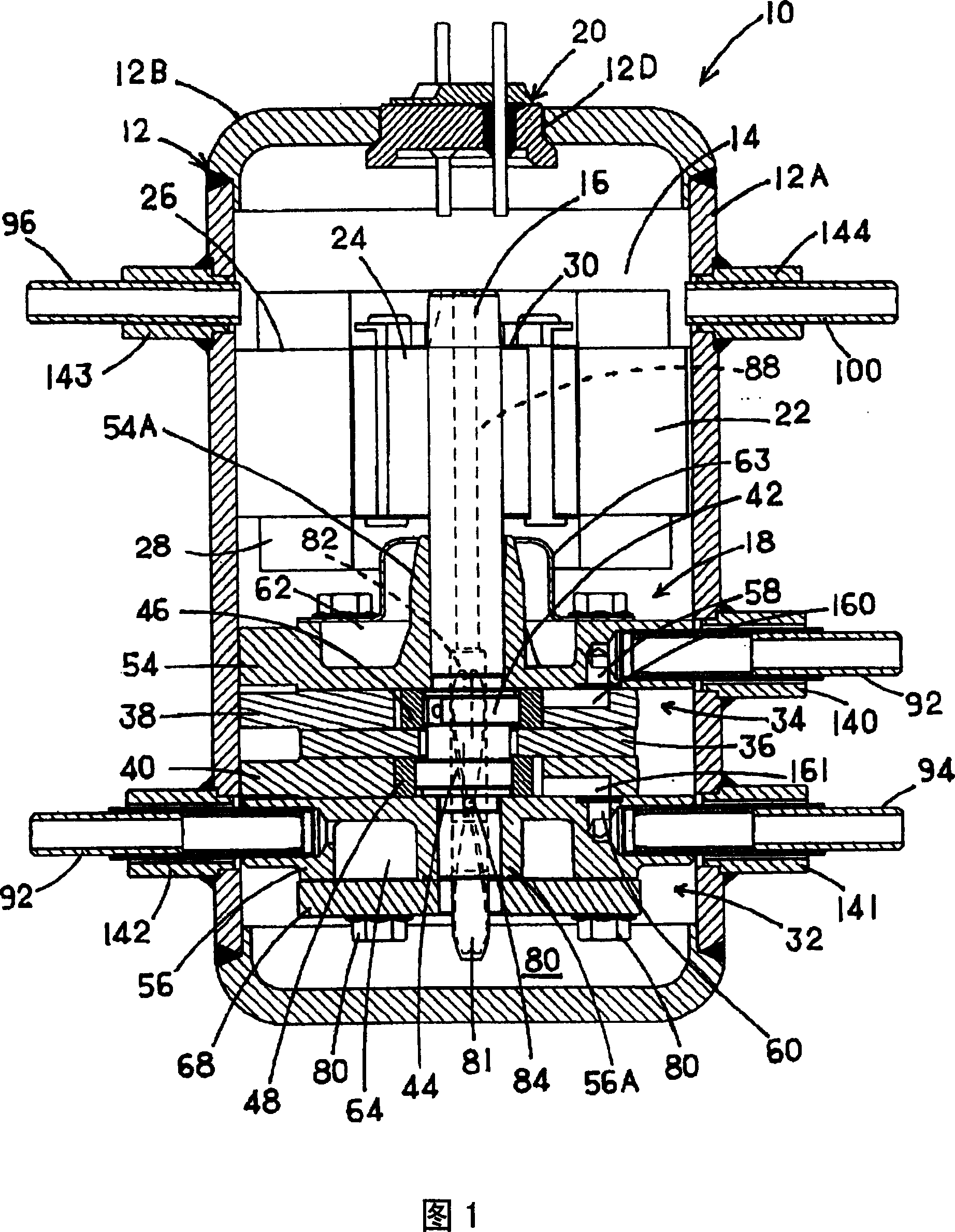
[0024] Hereinafter, embodiments of the rotary compressor of the present invention will be described in detail based on the drawings. 1 shows an embodiment of a refrigerant compressor according to the present invention, which includes an electric unit 14 as a drive unit and a rotary compression mechanism 18 as a compression unit driven by the electric unit 14 in a closed container 12. A longitudinal sectional side view of the machine 10.

[0025] In FIG. 1 , the rotary compressor 10 of this embodiment is an internal high-pressure type rotary compressor: the rotary compression mechanism part 18 is constituted by the first and second rotary compression units 32 and 34, and the rotary compressor compressed by the first rotary compression unit 32 The refrigerant sucked into the second rotary compression unit 34 is compressed, and discharged into the airtight container 12 , and then discharged to the outside of the airtight container 12 .

[0026] The airtight container 12 is compo...


PUM


Abstract

An object is to provide a refrigerant compressor which solves a disadvantage that an oil flows into a refrigerant circuit in the outside of the refrigerant compressor during introduction of the oil and which minimizes an amount of the oil to be introduced and which can secure a sufficient amount of the oil, and a refrigerant cycle device including the refrigerant compressor. A rotary compressor (refrigerant compressor) comprises, in a sealed container (12), an electromotive element (14) as a driving element, and a rotary compression mechanism part (18) driven by this electromotive element (14) and constituted of first and second rotary compression elements (32,34), and discharges a refrigerant compressed by the rotary compression mechanism part (18) from the sealed container, the compressor further comprising an oil reservoir (80) constituted in a bottom part of the sealed container; and a servicing pipe (100) attached to the sealed container to introduce the refrigerant and the oil into the sealed container.

Description

technical field [0001] The present invention relates to a refrigerant compressor equipped with a drive unit and a compression unit driven by the drive unit in an airtight container, and to discharge the refrigerant compressed by the compression unit to the outside of the airtight container, and a refrigeration compressor equipped with the refrigerant compressor. Agent circulation device. Background technique [0002] Conventionally, such a refrigerant cycle device including a refrigerant compressor constitutes a refrigerant circuit by sequentially connecting a refrigerant compressor, a radiator, a capillary tube (throttling mechanism), an evaporator, and the like in an annular manner. Such a refrigerant compressor is configured, for example, in a rotary compressor including a drive unit and a rotary compression unit driven by the drive unit in an airtight container, and refrigerant gas is sucked into the drive cylinder from the suction port of the rotary compression unit. T...

Claims


Application Information

Patent Timeline
Patent Type & Authority Applications(China)
IPC IPC(8): F04C18/00F25B1/00
CPCF25B45/00F25B9/008F04B39/023F25B1/04F25B31/002F04B39/123F04C18/356F04C2240/806F04C2240/809F04C29/00F04C29/02
Inventor 里和哉
Owner SANYO ELECTRIC CO LTD
Why Eureka
Try Eureka