Touch sensing costume for intelligent robot

A technology of intelligent robot and tactile sensing, which is applied in the testing of machines/structural components, measuring devices, and the measurement of the properties and forces of piezoresistive materials, etc., can solve the problems of high cost and poor flexibility of tactile sensitive units, and achieve Low cost, good flexibility, and large detection area

Inactive Publication Date: 2007-04-04
CHONGQING UNIV
View PDF0 Cites 36 Cited by
  • Summary
  • Abstract
  • Description
  • Claims
  • Application Information

AI Technical Summary

Problems solved by technology

In these existing sensing methods and devices thereof, there are two common deficiencies: one is that the cost of the tactile sensitive units in these sensing devices is relatively high, and if all parts of the human body that need to be cared about are correspondingly installed For the tactile sensitive units in these sensing devices, it is necessary to increase many identical or different tactile sensitive units
If the cost is placed in a secondary position and the area of ​​the corresponding tactile sensing part is increased by increasing the number of existing tactile sensing units, the second deficiency is that the flexibility of the larger area of ​​the tactile sensing part is relatively poor.

Method used


Image

  • Touch sensing costume for intelligent robot
  • Touch sensing costume for intelligent robot
  • Touch sensing costume for intelligent robot

Examples


Embodiment 1

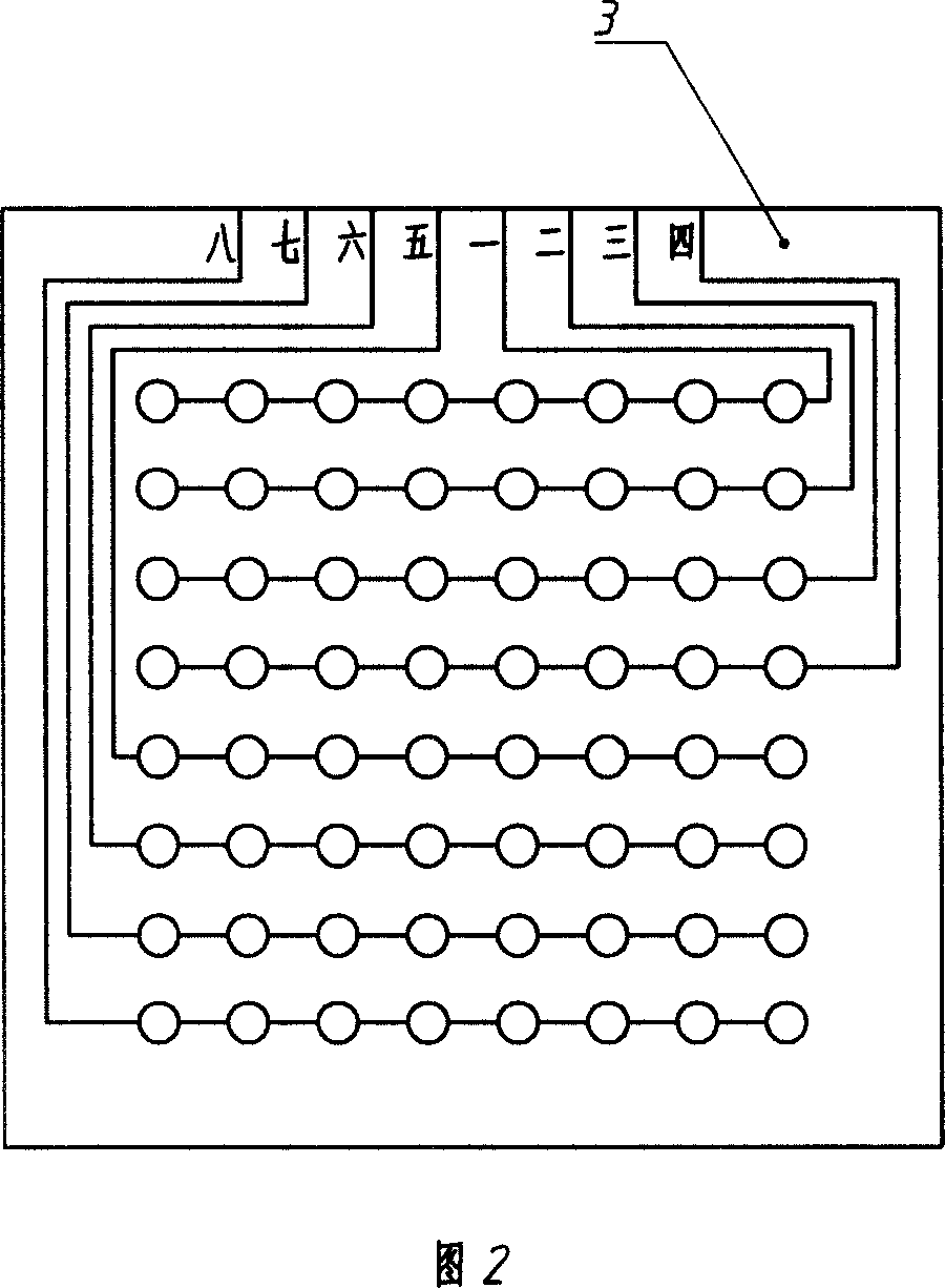
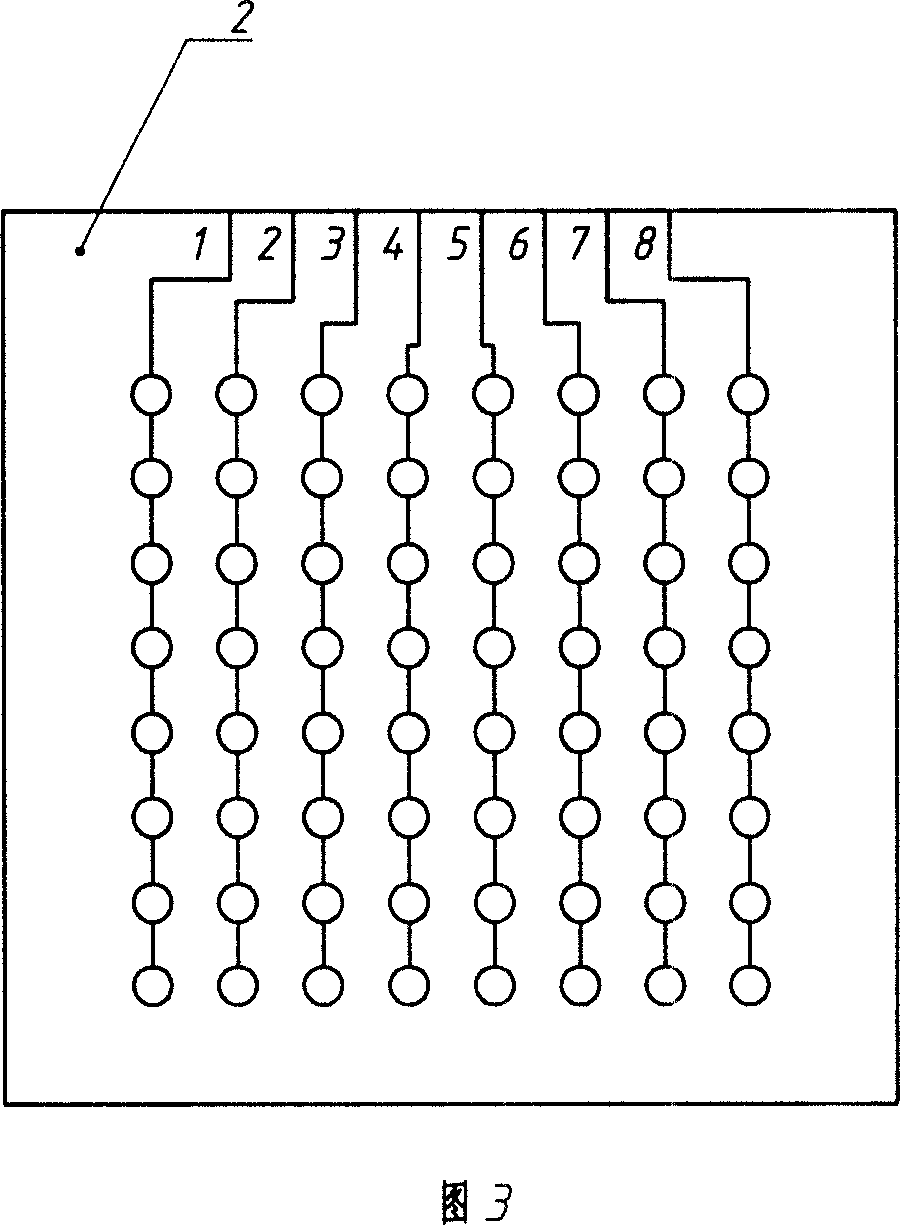
[0018] This example is based on the general description of the specific embodiments, and is a further example of the production of the thin film electrode plate and the material of the conductive rubber 20 (refer to FIGS. 2 , 3 , 4 ). In this example, the thin film electrode plate is to print silver paste on one side of the PB plastic film to form the corresponding determinant array electrode contacts (in view of the specific process of printing silver paste is a known and common technology, so in this example not further described). The conductive particles in the conductive rubber 20 of this example are glass balls plated with silver. Apparently, the conductive particles in the conductive rubber 20 can also be aluminum-plated silver or carbon black-selected according to material sources and / or other requirements.

Embodiment 2

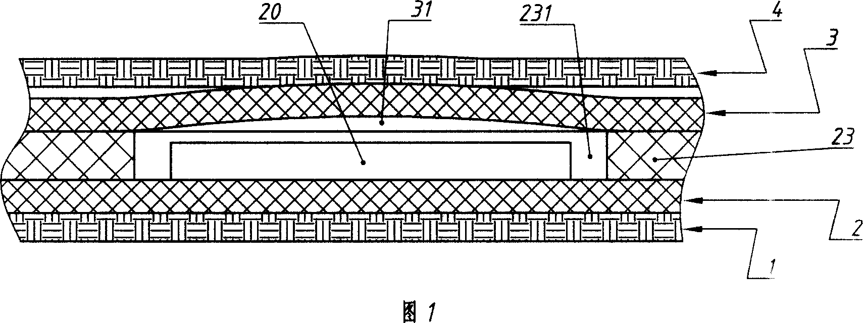
[0020] This part is based on the general description of specific embodiments or the first embodiment, and introduces the geometry and further features of the conductive rubber 20 and the insulating film spacer 23 (refer to FIGS. 1 and 4 ). Specifically, each piece of conductive rubber 20 is a round cake shape, and the holes 231 that cover them on the insulating film spacer 23 are circular holes. 23 are all pressed to the thinnest, the gap that still can not scratch between the two. That is to say, when the conductive rubber 20 is under pressure, the amount of compression that causes the change of its resistance value will not be disturbed by the insulating film spacer 23, which improves the accuracy and reliability of the present invention. At each electrode contact of the upper film electrode plate 3, there is a bubble 31 that is concave inward and protrudes outward on its opposite face (using a known hot-pressing bubble technology), and the center of the electrode contact, t...

Embodiment 3

[0024] This example is based on the general description of specific embodiments, Example 1 or Example 2, and is a supplementary improvement made to improve the durability and reliability of the present invention (refer to Figures 1 and 4). Its material is respectively the protective layer (this example uses waterproof cloth) of tarpaulin, plastic film or rubber skin on the outside of two film electrode plates (2,3) up and down. The lower protective layer 1, the lower thin-film electrode plate 2, the insulating film spacer 23, the upper thin-film electrode plate 3 and the upper protective layer 4 are pasted together by flexible glue in sequence. The flexible glue refers to the glue that still has a certain degree of flexibility after the glue is cured and coagulated (such as glue such as neoprene). In this way, the tactile sensing clothing of the intelligent robot has a certain softness in terms of bonding materials.

[0025]In this example, the conductive rubber 20 is pasted ...


PUM

PropertyMeasurementUnit
diameteraaaaaaaaaa
thicknessaaaaaaaaaa

Abstract

A tactile sensing garment of intelligent robot consists of garment wearing on intelligent robot and tactile sensing unit set on said garment. It is featured as forming said tactile sensing unit by both top and bottom film electrode plates with each electrode contact being corresponded one by one as well as with one electrode contact being arranged in line array form and another one being arranged in column array mode, sticking a conductive rubber on each electrode contact of bottom film electrode plate and setting a backing strap with holes corresponding to said conductive rubber between two said film electrode plates.

Description

technical field [0001] The invention relates to a tactile sensing device for an intelligent robot, in particular to a tactile sensing device worn on an intelligent robot. Background technique [0002] In some crash tests involving the human body (for example, the crash test of a manned car), or other tests with contact pressure that may cause harm to the human body, in order to avoid the real body from being hurt, people often use the sensor with the corresponding sensory ability intelligent robots to replace the human body for experiments. For this reason, people will install some tactile sensing devices on the relevant parts of the intelligent robot for sensing the size of the pressure. Through these tactile sensing devices, the parts of the human body that may be impacted and the magnitude of the impact force on these parts are detected, thereby providing a basis for improving the design of products (for example, passenger vehicles). Among the tactile sensing methods an...

Claims


Application Information

Patent Timeline
Patent Type & Authority Applications(China)
IPC IPC(8): G01L1/18G01M7/08
Inventor 秦岚李青潘英俊孙先逵刘颖
Owner CHONGQING UNIV
Why Eureka
Try Eureka