
Method and device for gasifying water

An aerator and gas technology, applied in mixing methods, distribution devices, transportation and packaging, etc., can solve the problems of foam formation temperature, fluctuation, etc., achieve high release speed, and avoid complete failure.

Inactive Publication Date: 2007-04-04
马格列特·施皮格尔
View PDF0 Cites 10 Cited by
  • Summary
  • Abstract
  • Description
  • Claims
  • Application Information

AI Technical Summary

Problems solved by technology

All manufacturers of such equipment face the same problems of foam formation and temperature fluctuations

Method used

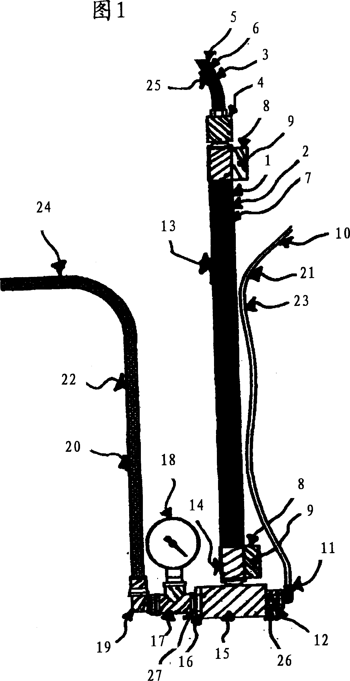

Image

  • Method and device for gasifying water
  • Method and device for gasifying water
  • Method and device for gasifying water

Examples


Embodiment Construction

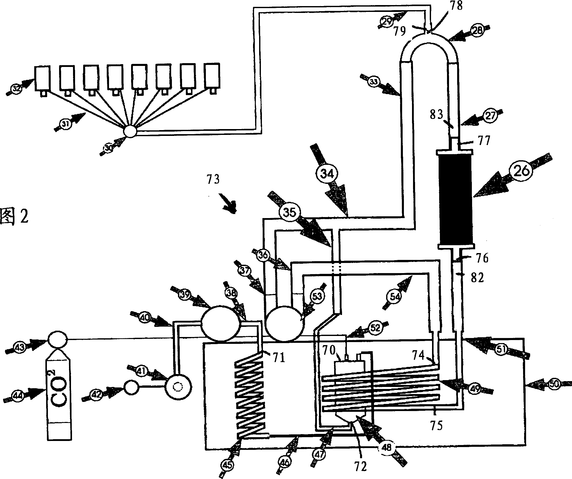
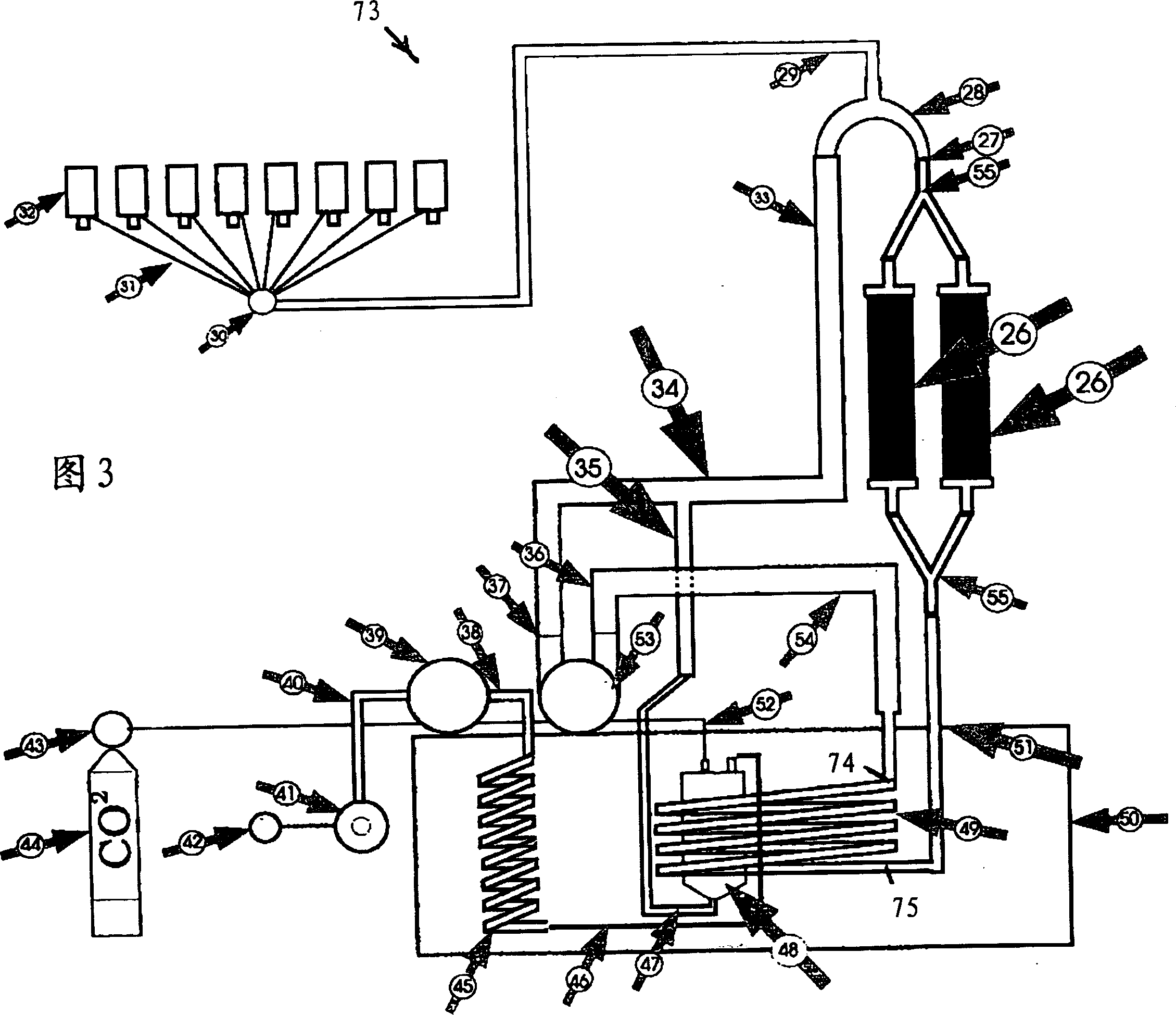
[0026] The device used to add gas to the liquid mainly includes a CO 2 When aerated, it is defined as the aerated container of the carbonation container 48, one when using CO 2 The in-line aerator and pressure lift pump 39 , gas supply 44 , bleed point 32 , housing 50 , first cooler 45 and second cooler 49 are defined as in-line carbonator 26 when aerated. The first cooler 45 is connected to the upper closure cover 70 of the carbonation vessel 48 through the connection pipe 46 , this cover has a channel extending into the interior cavity of the carbonation vessel 48 . In this cavity, the cold water supplied to the carbonation container through the connection pipe 46 is mixed with the gas supplied from the gas supply device 46 to the inside of the carbonation container 48 through the supply pipe 52 and the upper closure cap 70 .

[0027] The first cooler 45 is connected at its upper end 71 remote from the connecting pipe 46 to the inlet pipe 40 , through which liquid is suppli...


PUM


Abstract

The invention relates to a method during which, for intensifying a binding of gas to a water gasified inside at least one gasifying vessel, a gas / water mixture leaving the gasifying vessel is, after leaving the gasifying vessel, led through at least one gasifier connected downstream from the gasifying vessel and is intensively mixed therein. In a device, at least one in-line gasifier (26) for intensively mixing the gasified water into a flow consisting of gas and water, said flow being led through the in-line gasifier, is connected downstream from the gasifying vessel (48) at the outlet (47) thereof provided for the gasified water.

Description

technical field [0001] The invention relates to a method for enhancing the binding of gases in water, wherein the water is aerated in at least one aeration container. Furthermore, the invention relates to a device for enhancing the binding of gases in water, wherein the water is aerated in at least one aeration container. Background technique [0002] Certain methods for aerating liquids, especially CO 2 Method and apparatus for introduction into water. where water and CO 2 Fill into the carbonation container. It should be advantageous to generate CO in the carbonation vessel by means of different process steps, especially by means of atomizing the water 2 relationship with water. [0003] But the resulting carbonated water or other mixed CO 2 The drinks are unsatisfactory in many ways. On the one hand, the gas and water are only partially mixed, so when the gas-water mixture is introduced into the drinking vessel, the CO 2 The tiles often come out of the gas-water m...

Claims


Application Information

Patent Timeline
Patent Type & Authority Applications(China)
IPC IPC(8): B01F5/06B01F13/10B01F13/00B01F3/04B67D1/00A23L2/54B01F5/04C02F1/68
CPCB01F2003/04872B01F3/04815C02F1/68A23V2002/00B01F2003/04893B01F2003/04879B01F2003/049B01F5/0696B01F5/0403A23L2/54B01F2003/04865B67D1/0058B01F23/2363B01F23/23761B01F23/237611B01F23/237612B01F23/237621B01F23/23762B01F25/31B01F25/45241A23V2300/04
Inventor P·施皮格尔
Owner 马格列特·施皮格尔
Learn More