Supercharge Your Innovation With Domain-Expert AI Agents!

Method of displaying remaining battery power, and electronic apparatus

A technology of battery remaining power and display method, applied in battery circuit devices, measuring devices, circuit devices, etc., can solve the problems of high software development cost, high hardware cost, high power consumption, etc., and achieve direct value protection, cost reduction, The effect of preventing breakage

Inactive Publication Date: 2007-04-04
SONY GRP CORP
View PDF3 Cites 9 Cited by
  • Summary
  • Abstract
  • Description
  • Claims
  • Application Information

AI Technical Summary

Problems solved by technology

[0009] In the conventional technology, the authentication process of batteries used in the same type of electronic device is uniformly performed, so it is easy for those who want to manufacture counterfeit batteries to crack the authentication method of batteries
In addition, there is also the following problem: because the load on the microcomputer on the set side and the battery side is large, a high-speed driving microcomputer is required, resulting in high cost, and because the load on the microcomputer on the set side and the battery side is large , so it is necessary to drive the microcomputer at high speed, resulting in large power consumption
[0010] In addition, there is a problem that in the conventional battery pack, only one of the remaining battery power display function and the battery authentication processing function is mounted, and both functions are simultaneously carried out to simultaneously perform battery remaining power display and battery authentication. Processing requires two independent devices and a battery communication system, and the communication line requires two systems, resulting in high hardware costs. Moreover, the communication driver requires two systems, and the software development cost is high.

Method used


Image

  • Method of displaying remaining battery power, and electronic apparatus
  • Method of displaying remaining battery power, and electronic apparatus
  • Method of displaying remaining battery power, and electronic apparatus

Examples


Embodiment Construction

[0024] Hereinafter, embodiments of the present invention will be described in detail with reference to the drawings. In addition, the present invention is not limited to the examples described below, and can be appropriately changed within the scope of knowledge of those skilled in the art without departing from the gist of the present invention.

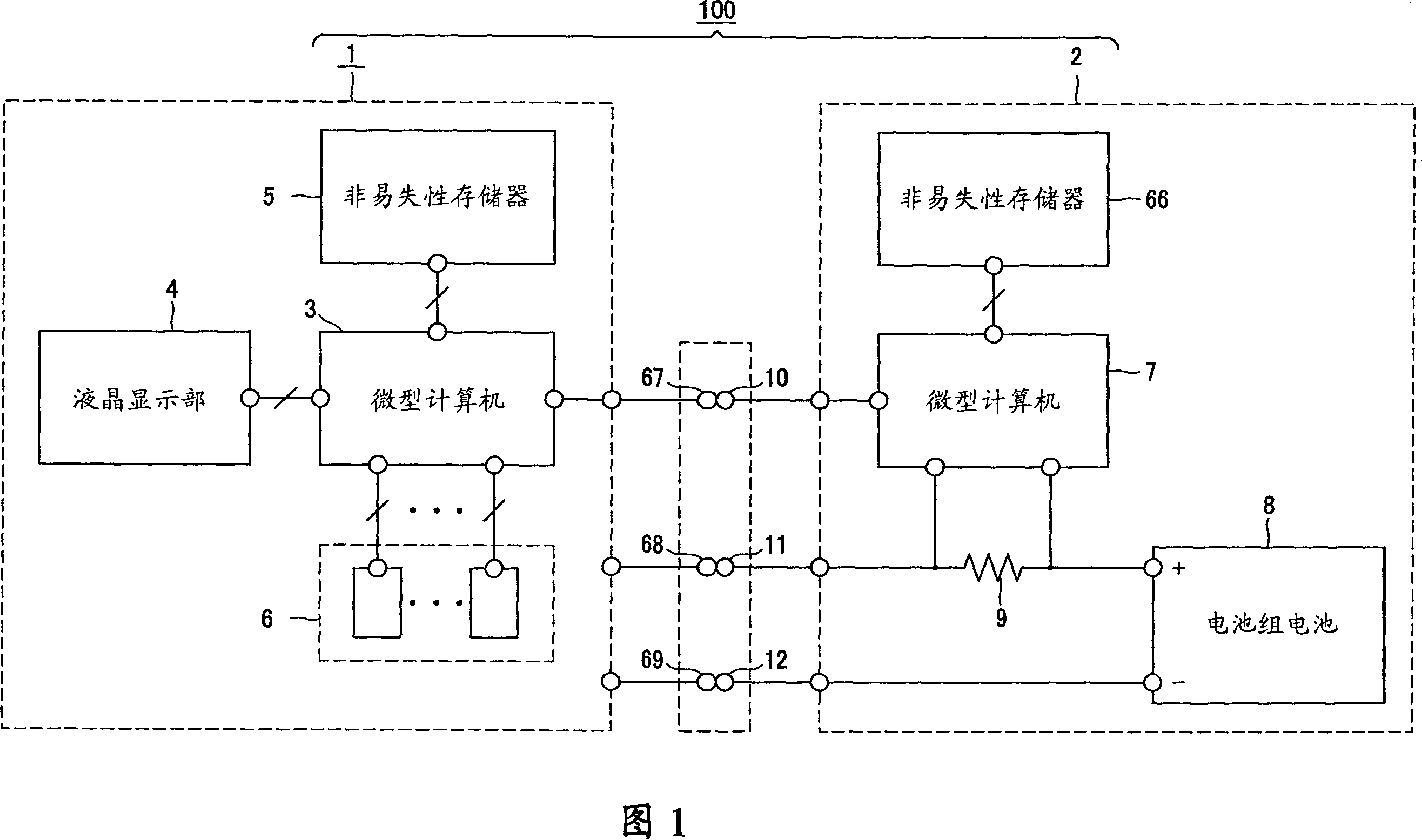
[0025] The present invention is applicable to, for example, the video camera 100 including the configuration shown in FIG. 1 . The video camera 100 includes: a camera body 1; and a battery pack 2 detachably attached to the camera body 1 and supplied with power through connection terminals.

[0026] The camera body 1 is provided with a first microcomputer 3 , a liquid crystal display 4 (LCD: Liquid Crystal Display), a nonvolatile memory 5 , and several other devices 6 required to configure the video camera 100 .

[0027] The first microcomputer 3 is connected to a liquid crystal display unit 4, a nonvolatile memory 5, and other devi...


PUM


Abstract

The present invention is directed to a battery residual quantity display method for performing display of battery residual quantity of a battery pack mounted at an electronic equipment and serving to supply power to the electronic equipment. When power is turned ON, a first microcomputer (3) of the camera body (1) side serves to first acquire, by serial communication, information for battery residual quantity display from a second microcomputer (7) of the battery pack (2) side loaded at the camera body to perform battery residual quantity display on the basis of the acquired information to subsequently acquire, by serial communication, information for authentication processing from the second microcomputer of the battery pack side to perform an authentication processing for judging on the basis of the acquired information as to whether or not the battery pack connected to the camera body is genuine battery pack to update, after the authentication processing, the content of the battery residual quantity display on the basis of information for battery residual quantity display acquired by serial communication from the microcomputer of the battery pack side.

Description

technical field [0001] The present invention relates to a method for displaying the remaining power of a battery in an electronic device and an electronic device using the display method. The electronic device includes: a device body equipped with a microcomputer with a communication function; A power supply is provided, and a microcomputer having a serial communication function with a microcomputer on the side of the device body is mounted on the device main body in a detachable manner. [0002] This application claims priority on the basis of Japanese Patent Application No. 2005-067818 for which it applied to Japan on March 10, 2005, and is incorporated in this application by referring to this application. Background technique [0003] Conventionally, electronic devices such as video cameras or digital cameras, mobile phones, or personal computers are often used as power sources from batteries containing secondary batteries such as lithium-ion batteries, NiCb batteries, an...

Claims


Application Information

Patent Timeline
Patent Type & Authority Applications(China)
IPC IPC(8): G01R31/36G06F1/26G06F1/28H01M2/10H01M10/48
CPCH01M10/4221G01R31/3682G06F1/3203G06F21/81H01M10/48H04L63/08H01M10/4257H01M10/488Y02B60/1292G01R31/3646Y02E60/10G06F1/28H01M50/204G06F1/26
Inventor 中岛良一佐藤秀幸土谷之雄绳和泰
Owner SONY GRP CORP
Features
  • R&D
  • Intellectual Property
  • Life Sciences
  • Materials
  • Tech Scout
  • Unparalleled Data Quality
  • Higher Quality Content
  • 60% Fewer Hallucinations
Learn More