
Device for use in a frequency hopping system

A device, frequency hopping technology, applied in transmission systems, electrical components, etc., can solve problems such as poor overall performance, inflexible use of hopping sequences, less frequency replacement or frequency migration, etc.

Inactive Publication Date: 2012-12-12
DSP GROUP SWITZERLAND
View PDF1 Cites 0 Cited by
  • Summary
  • Abstract
  • Description
  • Claims
  • Application Information

AI Technical Summary

Problems solved by technology

Further, this sequence has the disadvantage of being inflexible: in order to maintain lock as resistant to interference as possible, the sequence should be longer: a longer sequence mitigates the ill effects of the interfered channel compared to a shorter sequence
But to be as immune to interference as possible to get an active connection, the sequence should be short: a shorter sequence requires less frequency substitution or shifting to remove the interfered channel than a longer sequence
[0005] The disadvantage of the existing equipment is also that due to the inflexible use of hopping sequences, this equipment has a relatively poor overall performance

Method used


Image

  • Device for use in a frequency hopping system
  • Device for use in a frequency hopping system
  • Device for use in a frequency hopping system

Examples


Embodiment Construction

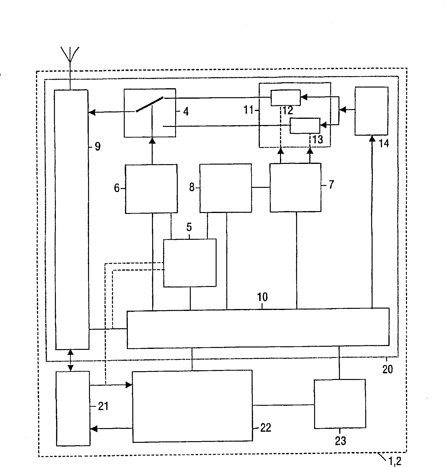
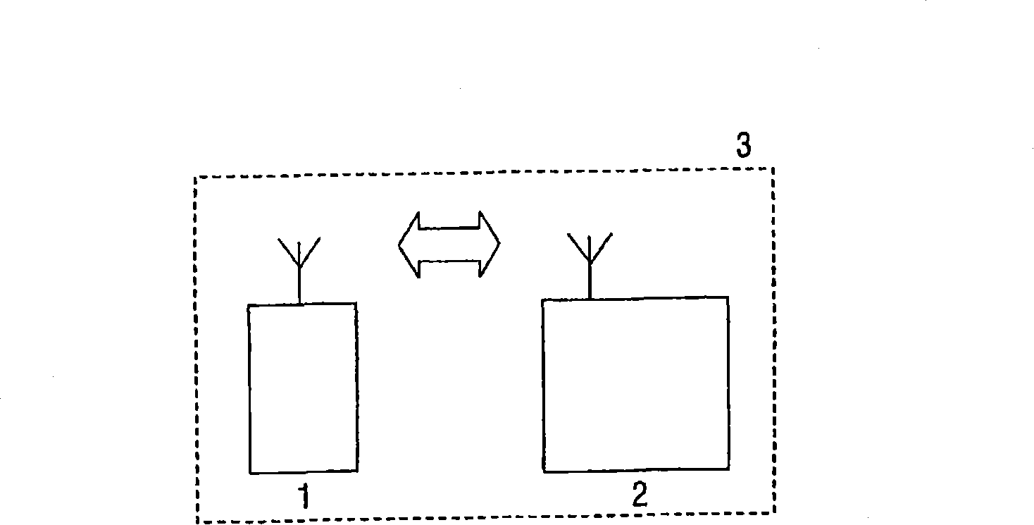
[0029] according to figure 1 A device 1 , 2 according to the invention shown in FIG. 2 , eg a terminal device 1 or a portable part or a station device 2 or a stationary part, contains a circuit 20 .

[0030] Circuitry 20 includes transceiver 9 coupled to an antenna. The control input of the transceiver 9 is coupled to the output of the selector 4, the control input / output of the transceiver 9 is coupled to the control input / output of the processor system 10 by a link. The processor system 10 includes, for example, a processor and a memory. A first input of the selector 4 is coupled to a first field 12 of a memory 11 for storing a first (longer) sequence of frequencies. A second input of the selector 4 is coupled to a second field 13 of the memory 11 for storing a second (shorter) frequency sequence. The first and second fields 12 and 13 are further coupled to the output of a counter 14 . A control input of counter 14 is coupled to a control output of processor system 10 . ...


PUM


Abstract

Devices ( 1,2 ) for use in frequency hopping systems ( 3 ) for frequency hopping through frequencies of a sequence of frequencies get a better overall performance by introducing selectors ( 4 ) for selecting the sequence from a number of sequences, which number of sequences comprises a first sequence and a second sequence, which first sequence is longer than the second sequence. Generators ( 7 ) generate the first and second sequences. Monitors ( 5 ) monitor channels in use and controllers ( 6 ) control the selectors ( 4 ) for, in a first mode, selecting the first sequence and for, in a second mode, selecting the second sequence in dependence of a monitoring result. Modifiers ( 8 ) modify the second sequence. The second sequence may form a subset of the first sequence. This all results in an increased overall quality and a reduced power consumption.

Description

technical field [0001] The invention relates to a device for use in a frequency hopping system, and also to a frequency hopping system, a circuit for the device, a method, a processor program product and a radio frequency signal. [0002] Examples of such equipment are terminals or portable units and stations or fixed units in digital cordless telephone systems. Background technique [0003] A prior art arrangement is known from WO 00 / 74257 A1, which describes a method for frequency acquisition in a frequency hopping system. In this frequency hopping system, the transmitter hops continuously in a predetermined and fixed sequence of N (N>=2) frequencies. The receiver stores the same sequence of N frequencies, but initially does not know which of the multiple frequencies is being used. Therefore, the receiver must detect this frequency and synchronize to the phase of the sequence. [0004] Therefore, the prior art sequence is fixed: it contains a fixed number of fixed fr...

Claims


Application Information

Patent Timeline
Patent Type & Authority Patents(China)
IPC IPC(8): H04B1/715H04B1/7156H04B1/713
CPCH04B1/7156H04B2001/7154H04B1/715H04B1/40
Inventor 奥特马尔·朗格尔特
Owner DSP GROUP SWITZERLAND
Learn More