Variable length coding method and variable length decoding method

A decoding method and variable technology, applied in the direction of code conversion, television, electrical components, etc., can solve problems such as coding units that fully remove redundant information

Inactive Publication Date: 2007-04-11
GK BRIDGE 1
View PDF8 Cites 2 Cited by
  • Summary
  • Abstract
  • Description
  • Claims
  • Application Information

AI Technical Summary

Problems solved by technology

[0096] In addition, the decoding unit RLD0a of the conventional image decoding device 202a or the run-length decoding unit RLD0b or RLD0c of the conventional image decoding device 202b or 202c corresponds to a variable-length coding process for the quantization coefficient that cannot sufficiently remove the Coding unit of redundant information in the quantization coefficient
[0097] Also, for changing the variable length coding table (VLC table) according to the numerical ...

Method used


Image

  • Variable length coding method and variable length decoding method
  • Variable length coding method and variable length decoding method
  • Variable length coding method and variable length decoding method

Examples


Embodiment 1

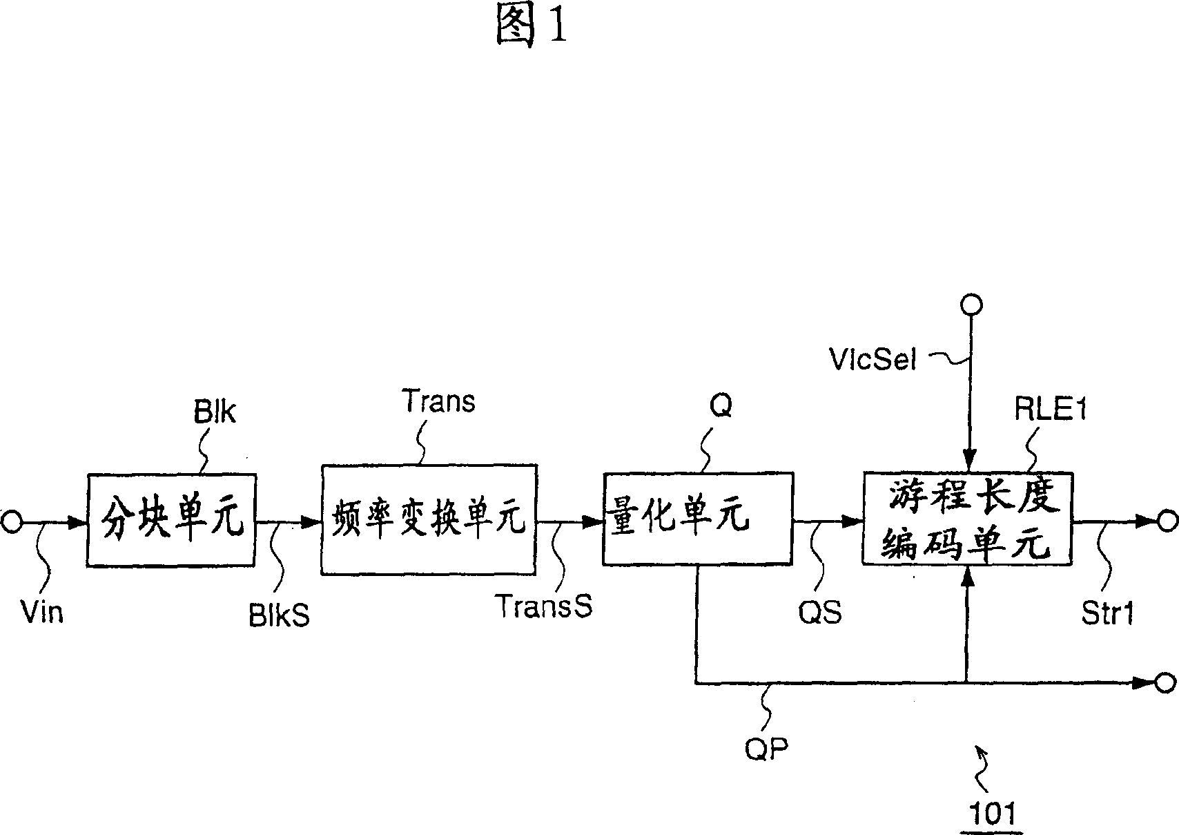
[0199] FIG. 1 is a block diagram for explaining an image coding apparatus according to a first embodiment of the present invention.

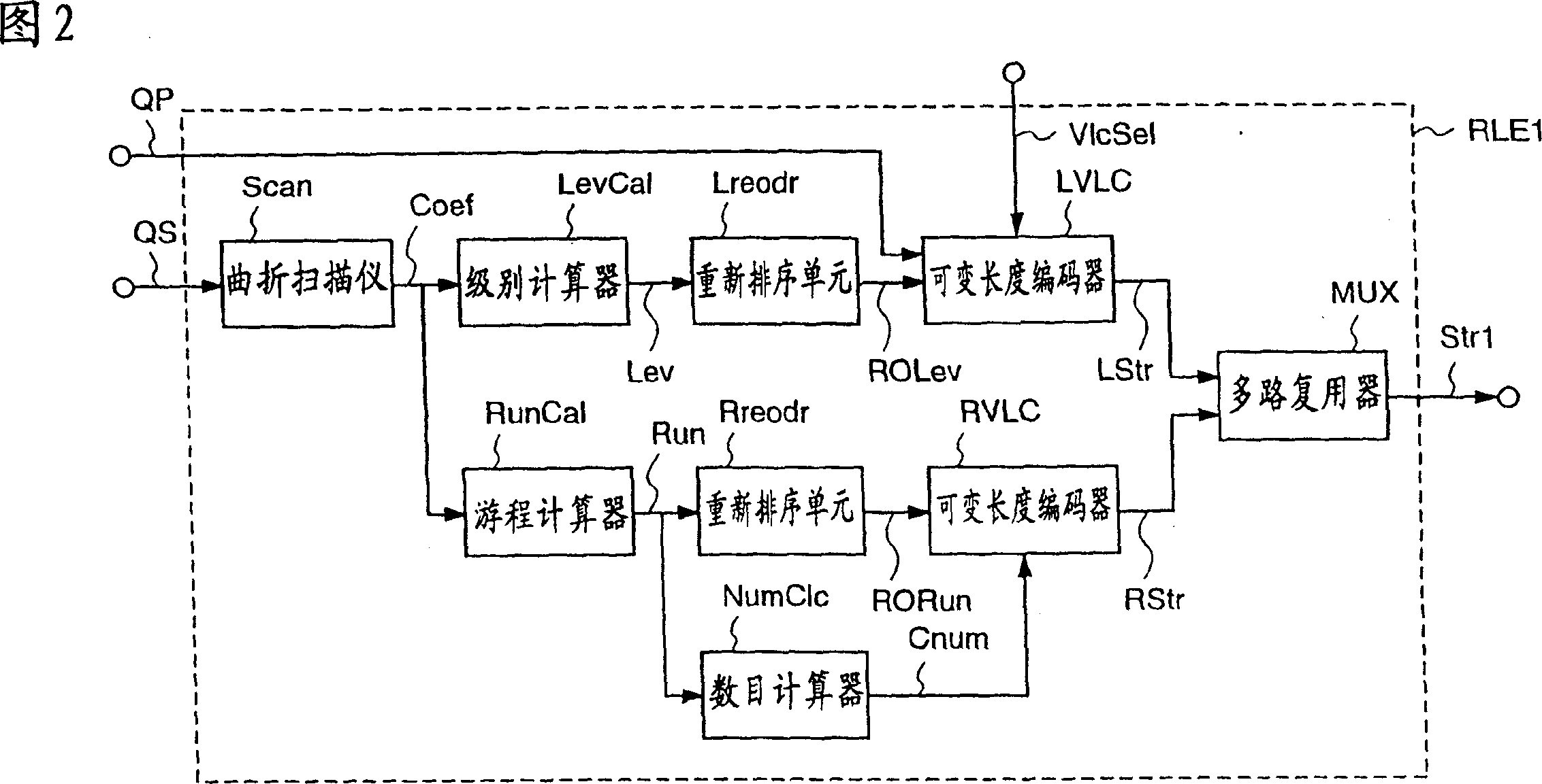
[0200] The image encoding device 101 according to the first embodiment has a run-length encoding unit RLE1 for subjecting the output QS from the quantization unit Q to variable-length encoding processing and outputting one encoded stream Str1 in accordance with the quantization parameter QP and the VLC selection signal VlcSel, instead of The run-length encoding unit RLE0b in the conventional image encoding device 201b as shown in FIG. 3 subjects the output (quantization component) QS from the quantization unit Q to variable-length encoding processing and outputs an encoded stream Str0b.

[0201] Here, the quantization parameter QP is a parameter representing a value of one quantization step, and the quantization step is approximately proportional to the quantization parameter QP. More specifically, when the quantization parameter QP is large, th...

Embodiment 2

[0250] Fig. 9 is a block diagram for explaining an image decoding apparatus according to a second embodiment of the present invention.

[0251] The image decoding device 102 according to the second embodiment decodes, for example, the encoded stream Str1 output from the image encoding device 101 of the first embodiment.

[0252] The image decoding device 102 has a run-length decoding unit RLD1 that subjects the input encoded stream Str1 to variable-length decoding processing to reconstruct quantized coefficients based on the quantization parameter QP and the VLD selection signal VldSel, instead of the A run-length decoding unit RLD0b that subjects the input encoded stream Str0b to variable-length decoding processing. The structure is the same as that of the image decoding device 202b shown in FIG. 36 except for the run-length decoding unit RLD1.

[0253] Fig. 10 is a block diagram for explaining a specific structure of the run-length decoding unit RLD1.

[0254] The run-leng...

Embodiment 3

[0283] Fig. 13 is a block diagram for explaining an image coding apparatus according to a third embodiment of the present invention.

[0284] The image coding device 103 according to the third embodiment has a run-length coding unit RLE2 that subjects the output QS from the quantization unit Q to variable-length coding processing and outputs one coded stream Str2 according to the quantization parameter QP or the VLC selection signal VlcSel, which replaces the The run-length encoding unit RLE0c in the image encoding device 201c shown in FIG. 38 subjects the output (quantized component) QS from the quantization unit Q to variable-length encoding processing and outputs an encoded stream Str0c. Other parts of the image encoding device 103 of this third embodiment are the same as the conventional image encoding device 201c.

[0285] More specifically, similar to the conventional run-length encoding unit RLE0c, this run-length encoding unit RLE2 has a first code table T1 (see FIG. 4...


PUM


Abstract

According to the present invention, an image coding apparatus (103) that encodes quantized coefficients corresponding to an image signal as target data to be processed is provided with a run-length encoding unit (RLE2) that assigns variable length codes to the quantized coefficients using code tables. The run-length encoding unit (RLE2) forms a second code table by optimizing a first code table to the target data to be processed, and selects one of the first and the second code tables as a code table that is to be employed for the assignment of the variable length codes in accordance with a quantization parameter (QP) or a variable length coding selection signal (VlcSel), whereby redundancy of information included in the target data to be processed can be effectively eliminated, and the compression ratio for the image signal or the like can be further increased.

Description

[0001] This application is a divisional application of a patent application with the application number 02813282.3, the filing date being November 22, 2002, and the invention title being "Variable Length Coding Method and Variable Length Decoding Method". technical field [0002] The present invention relates to a variable length coding method and a variable length decoding method, and more particularly to a method for converting multiple data obtained by quantizing frequency components (quantization coefficients) of image data into coded data according to variable length coding processing. coefficients, and methods for decoding the encoded data to reconstruct coefficients according to a variable length decoding process. Background technique [0003] In recent years we have ushered in the multimedia age in which audio, video, and other data are processed integrally, and traditional information media such as newspapers, magazines, television, radio, and telephones (i.e., used ...

Claims


Application Information

Patent Timeline
IPC IPC(8): H04N7/50H04N7/30H04N7/26H03M7/40H03M7/46H04N19/13H04N19/136H04N19/162H04N19/176H04N19/18H04N19/61H04N19/69H04N19/89H04N19/93
Inventor 角野真也近藤敏志羽饲诚安倍清史
Owner GK BRIDGE 1
Why Eureka
Try Eureka