
Embossed tufting needle

A tufting needle and needle handle technology, which is applied in the field of improved tufting needles, can solve the problems of wear through yarn grooves, limit the working life of tufting needles, miss empty grooves, etc., and achieve the effect of reducing wear loss.

Active Publication Date: 2010-06-16
GROZ BECKERT KG
View PDF4 Cites 0 Cited by
  • Summary
  • Abstract
  • Description
  • Claims
  • Application Information

AI Technical Summary

Problems solved by technology

If such wear becomes excessive or even causes the guide grooves to wear out, the tufting needles need to be replaced
This limits the working life of the tufting needles
[0006] During the above process, due to unreliability in handling it may happen that the loop gripper rests on the side of the tufting needle and thus misses the empty groove

Method used


Image

  • Embossed tufting needle
  • Embossed tufting needle
  • Embossed tufting needle

Examples


Embodiment Construction

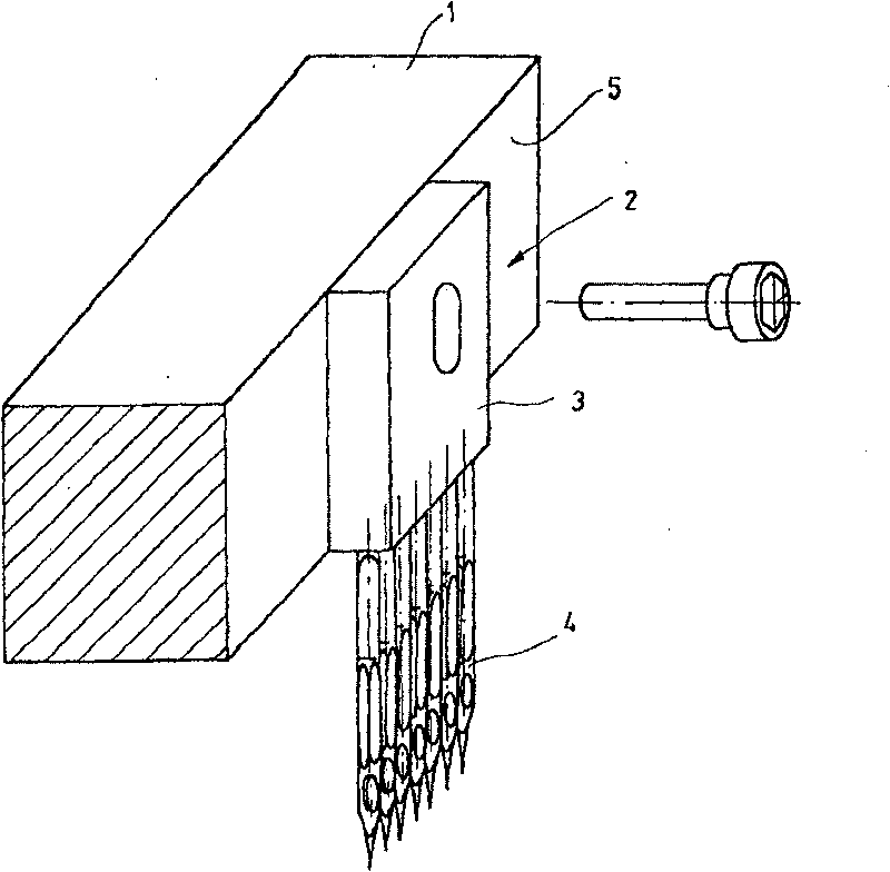
[0026] figure 1 A needle board 1 supporting a tufting module 2 is schematically shown. The tufting module 2 includes a main body 3 in which or on which a set of tufting needles is clamped. The main body 3 rests on the front side 5 of the needle plate 1 with flat flat sides. The tufting needles 4 are spaced parallel to each other and point downwards.

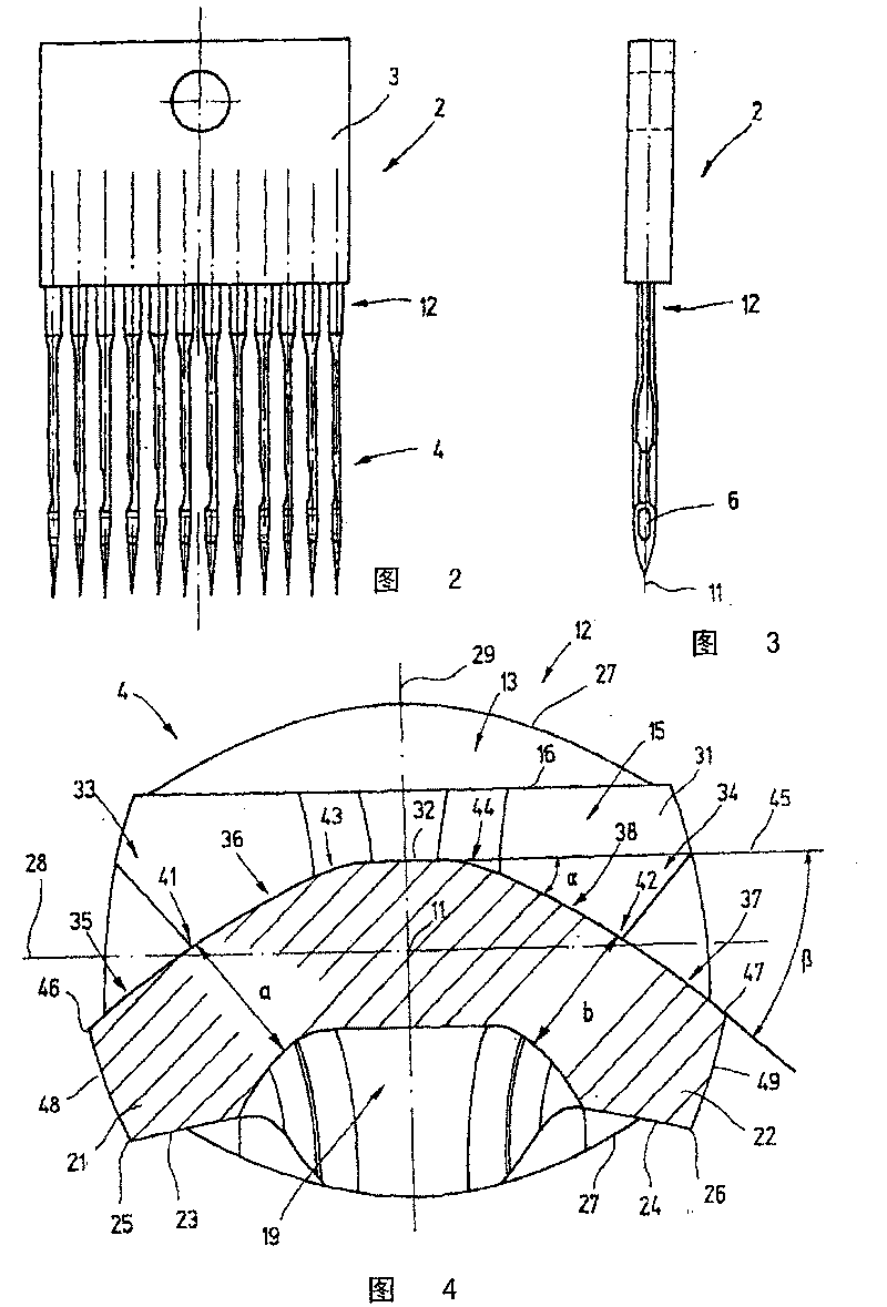
[0027] figure 2 and 3 The tufting modules 2 are shown respectively. like figure 2 As shown, the tufting needles 4 have the same structure and are flattened. They are clamped in the body 3 at their upper end. like image 3 As shown, their eyelets 6 are eg aligned with each other.

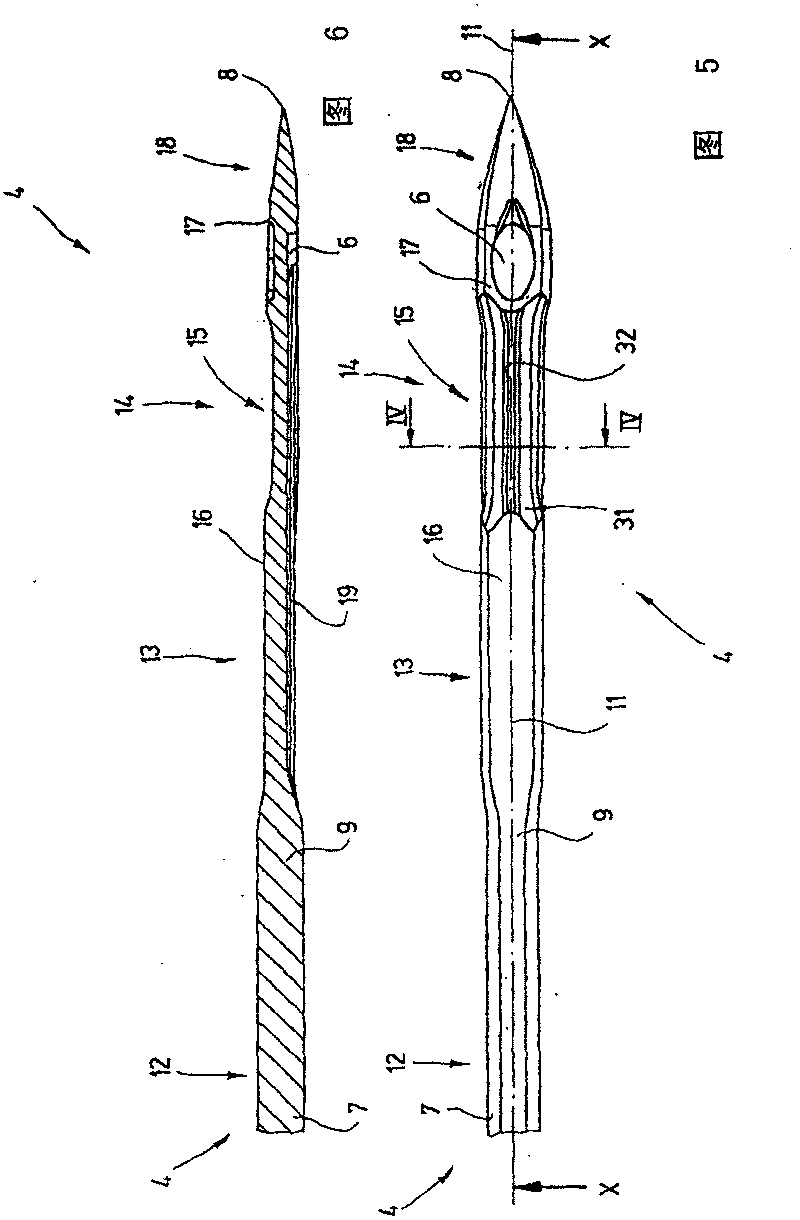
[0028] Figure 4 , 5 and 6 show the structure of a single tufting needle 4 . like Image 6 As shown, the tufting needle 4 has a needle body 7 constituting a shank 9 extending to a tip 8 marking the center of the shank 9 . A longitudinal axis 11 defining the longitudinal direction of the needle body 7 and the needle shaft 9 passes through...


PUM


Abstract

Disclosed is a novel tufting needle (4) that is characterized by a hollow groove (15) that is preferably embodied so as to be symmetric relative to a central plane (29) while being provided with chamfers (33, 34) on both sides. Said chamfers (33, 34) are provided with a small acute angle a relative to a reference plane (28) in an inner zone, i.e. a zone located near the central plane (29), while being inclined at a greater acute angle ss relative to the reference plane (28) in an outer zone lying adjacent to the border (edges 46, 47), thereby improving the rigidity, tufting properties, mechanical stability, and resistance to wear of the novel tufting needle (4).

Description

technical field [0001] The present invention relates to improved tufting needles. Background technique [0002] Tufting needles are known, for example, from European patent EP 0874932B1. The tufting needles described therein have a base body, the clamping end of which is clamped in the clamping body and whose other end terminates at the tip adjacent to the eye of the needle. In addition, the yarn guide groove extends along the needle shank to the eye of the needle. [0003] US Pat. No. VS-PS 5,189,966 discloses a tufting needle which has curved bevels on its sides for loop grippers. However, it does not have really empty grooves. In the region of the bevel the shaft has a cross-section shaped like a curved triangle. [0004] Furthermore, WO90 / 06391 discloses a tufting needle provided with a hollow groove near the eye of the needle. This empty groove provides better access to the yarn for a loop gripper or other tool. The tufting needles are flattened and mechanically w...

Claims


Application Information

Patent Timeline
Patent Type & Authority Patents(China)
IPC IPC(8): D05B85/00D05C15/20
CPCD05B85/00D05C15/20
Inventor B·E·希伦布兰德
Owner GROZ BECKERT KG
Learn More