Enclosed type electric and hydraulic floating force driving system

A buoyancy-driven, closed technology, applied in the field of marine engineering, can solve the task of observing the underwater environment that cannot meet long-term, continuous, large-scale and large-depth tasks, limit the scope of use and application fields, and reduce the diving depth of gliding submarines and other issues, to achieve the effect of light weight, compact structure and low manufacturing cost

Inactive Publication Date: 2007-04-25
SHENYANG POLYTECHNIC UNIV
View PDF2 Cites 17 Cited by
  • Summary
  • Abstract
  • Description
  • Claims
  • Application Information

AI Technical Summary

Problems solved by technology

Using a non-enclosed drive system will greatly reduce the diving depth of the gliding submarine, and it will not be able to dive to the deep sea to complete the task
In addition, the external medium directly contacts with the inside of the drive system to corrode the drive system and reduce the service life of the drive system
[0005] In the patent No. 200420109950.X of the utility model patent of the gliding submersible that uses the ocean temperature difference to drive the alkane engine, the ocean temperature difference is used as the power source of the gliding submersible, which is greatly affected by external environmental factors.
[0006] At present, underwater gliding submersibles can also use secondary energy (battery) as a power source, but this type of submersible must carry a power source for power supply, and the pressure-resistant cabin of the carrier has a small space and can only carry limited energy, which limits its use. The scope of use and application field cannot meet the long-term, continuous, large-scale and deep-water environmental observation tasks

Method used


Image

  • Enclosed type electric and hydraulic floating force driving system
  • Enclosed type electric and hydraulic floating force driving system

Examples


Embodiment 1

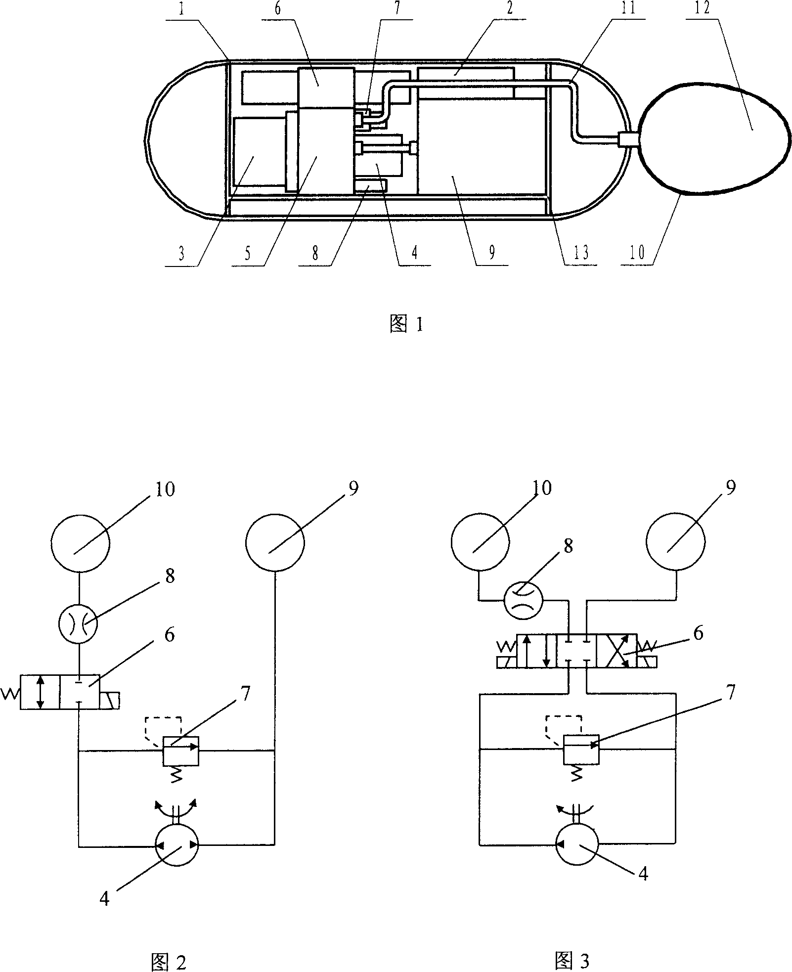
[0023] Embodiment 1: As shown in Figure 1, it includes an airtight pressure-resistant shell 1, an internal liquid medium tank 9, an external liquid medium capsule 10, and a liquid medium 12. The internal liquid medium tank 9 is located inside the airtight shell 1, and the external liquid medium capsule 10 is located outside the airtight housing 1, and is directly exposed to the external underwater environment; both the internal liquid medium tank 9 and the external liquid medium bag 10 are equipped with a liquid medium 12, which are communicated through a liquid medium pipeline 11, and the liquid medium 12 can be It flows between the internal liquid medium tank 9 and the external liquid medium bag 10. On the liquid medium pipeline 11, a hydraulic pump 4, a cut-off electromagnetic reversing valve 6, an overflow valve 7 and a flow meter 8 are integrated. On the integrated hydraulic block 5, the liquid medium pipeline 11 in the integrated hydraulic block 5 is connected. The integr...

Embodiment 2

[0031] Embodiment 2: Its structure is as shown in Figure 1, is identical with embodiment 1. The hydraulic pump 4 in this example adopts a one-way pump, and the cut-off electromagnetic reversing valve 6 is a three-position four-way valve without leakage. The specific pipeline connection relationship is shown in Figure 3: its pipeline connection relationship: hydraulic pump 4 The outlets of the valves are respectively connected with one port of the cut-off electromagnetic reversing valve 6 and the inlet of the overflow valve 7, and are connected with the external liquid medium bag 10 through the cut-off electromagnetic reversing valve 6 and the flow meter 8, and the inlets of the hydraulic pump 4 are respectively connected with the The outlet of the overflow valve 7 is connected to the other port of the cut-off electromagnetic reversing valve 6 , and is connected to the internal liquid medium tank 9 through the cut-off electromagnetic reversing valve 6 . This structure can effec...


PUM


Abstract

The invention relates to a sealed electric hydraulic driving system. Wherein, it comprises sealed pressure-resistance frame, inner liquid tank, and outer liquid bubble; the liquid tank are in the frame; the outer liquid bubble is outside the frame; the inner liquid tank and the outer liquid bubble are connected by liquid tube; the tube has hydraulic pump, stop electromagnetic steering valve, overflow valve and flux meter, integrated on the hydraulic block; said hydraulic block is integrated with direct-current motor; the motor and the hydraulic pump are connected; the direct-current power is connected to the motor. The invention has simple structure and high efficiency.

Description

technical field [0001] The invention relates to a closed electro-hydraulic buoyancy driving system, which belongs to the technical field of marine engineering. It provides power for the deep-sea underwater navigation carrier by changing the buoyancy, and serves as a power system for the buoyancy-driven underwater navigation carrier and underwater observation platform. Background technique [0002] Marine environmental observation is an important means for human beings to understand and understand the ocean, and it is also a prerequisite for the development and utilization of marine resources. Underwater observation platform technology is the basis for improving marine environment observation and marine resource development capabilities. At present, the long-term, continuous and large-scale underwater environment observation content includes physical parameters, marine geology and geophysics parameters, marine chemical parameters, marine biological parameters and on-site clo...

Claims


Application Information

Patent Timeline
Patent Type & Authority Applications(China)
IPC IPC(8): B63G8/24
Inventor 张禹王世杰苏东海胡俊宏
Owner SHENYANG POLYTECHNIC UNIV
Why Eureka
Try Eureka