Electromagnetic sliding valve

A sliding valve, electromagnetic technology, applied in the direction of valve details, multi-way valves, valve devices, etc., can solve the problems of difficult processing, complex structure, unfavorable open design, etc., to increase the function of electromagnetic valve, small compression, convenient Assembly effect

Active Publication Date: 2007-04-25
ZHEJIANG SANHUA INTELLIGENT CONTROLS CO LTD
View PDF2 Cites 16 Cited by
  • Summary
  • Abstract
  • Description
  • Claims
  • Application Information

AI Technical Summary

Problems solved by technology

[0023] The technical problem to be solved and the technical task put forward by the present invention are to overcome the defects of the prior art products such as difficult processing, complex structure, and unfavorable open design of the valve due to their structure, and to provide a new electromagnetic sliding valve

Method used


Image

  • Electromagnetic sliding valve
  • Electromagnetic sliding valve
  • Electromagnetic sliding valve

Examples


Embodiment 1

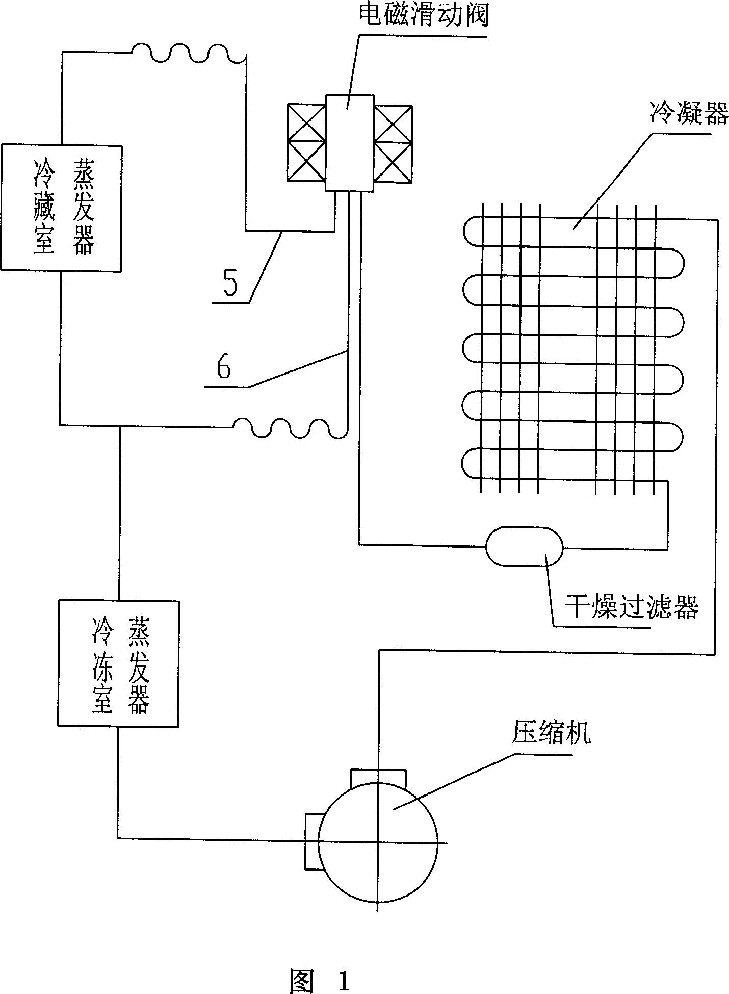
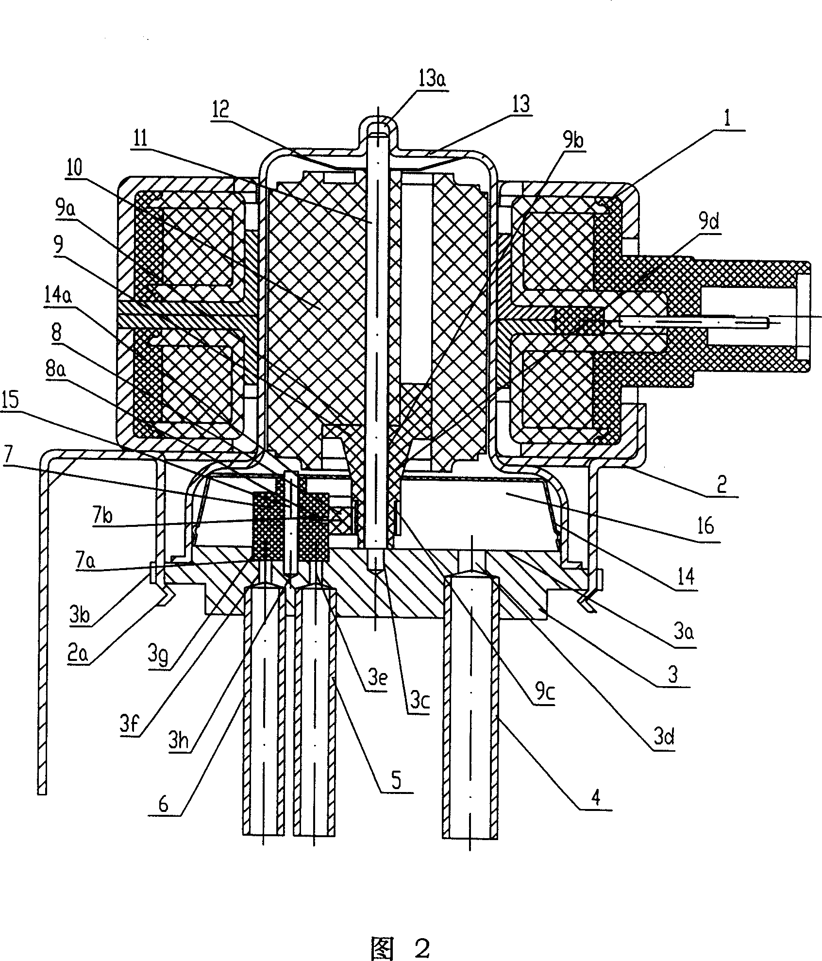
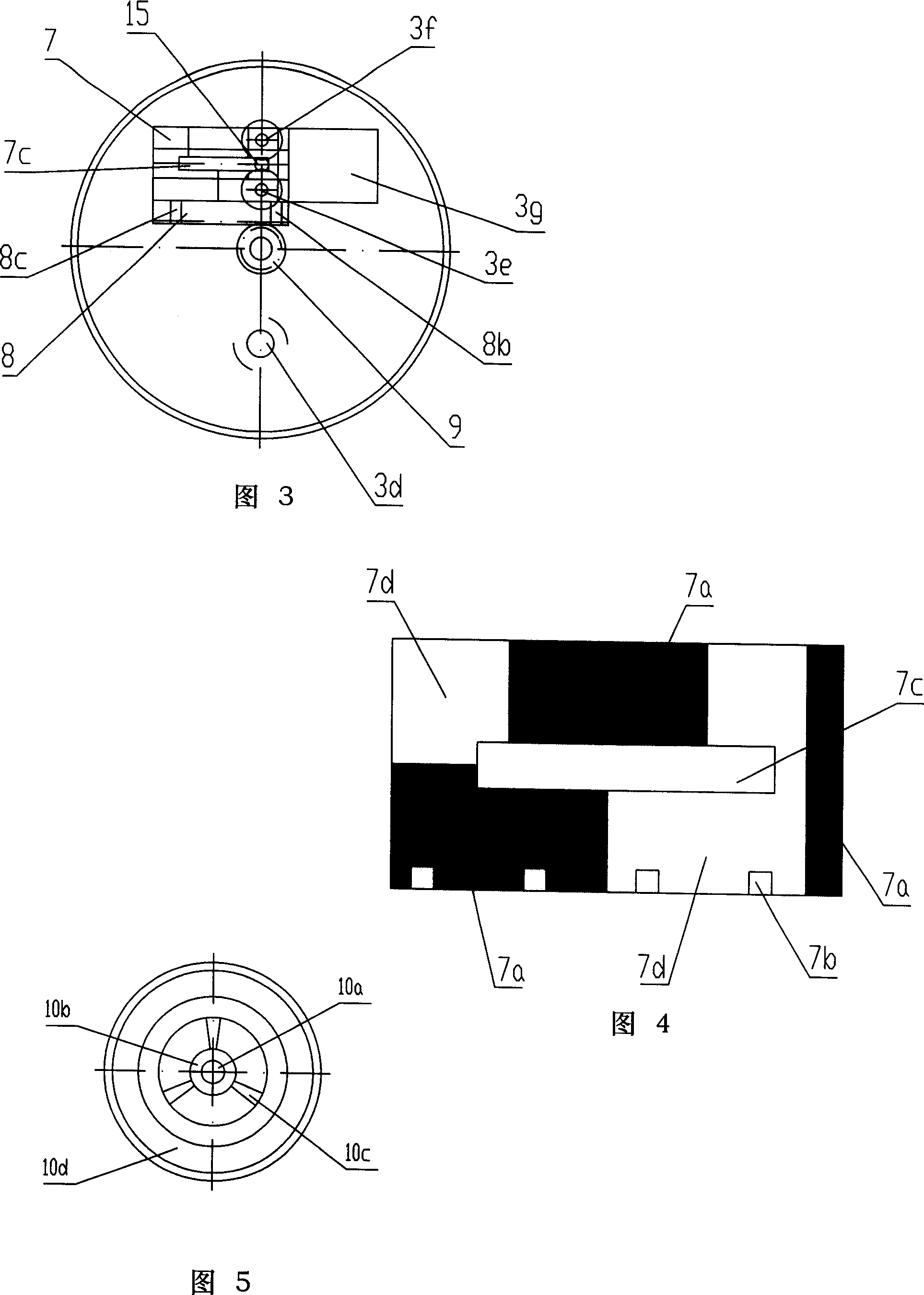
[0056] Referring to Figs. 2-5 and Fig. 11, the first embodiment of the present invention, one-inlet-two-outlet electromagnetic sliding valve, will be introduced below.

[0057] The electromagnetic sliding valve has a valve body part formed by sealingly connecting the valve seat part 3 and the outer cover 13 by means of welding or the like, and a valve cavity 16 formed thereby.

[0058] The electromagnetic sliding valve has a normally open inlet pipe 4 and two outlet pipes 5 and 6 that are opened and closed according to the function, a slider guide groove 3g, a central support shaft 11 and its supporting mechanism 3c, a slider guide shaft 15 and its The valve seat part 3 of the support mechanism 3h: the sealing surface 3a of the valve seat part 3 is provided with outlets 3e and 3f and an inlet 3d, the outlet 3e is connected to the outlet pipe 5, the outlet 3f is connected to the outlet pipe 6, and the inlet 3d Connecting the inlet pipe 4, the outlets 3e and 3f are distributed a...

Embodiment 2

[0089] Referring to Figures 6-10 and Figure 12, the one-inlet and three-outlet electromagnetic sliding valves will be introduced below.

[0090] 6 to 10 and FIG. 12 correspond to the parts in FIGS. 2 to 5 and FIG. 11 are assigned the same reference numerals as those in FIGS. 2 to 5 and FIG.

[0091] The valve body parts are driven and rotated by the stepping motor, and the solenoid valve can obtain four working positions as shown in Figure 12: (a) the first working position, the outlet 3f, the outlet 3e and the outlet 3i are all closed; (b ) the second working position, the outlet 3f is opened, the outlet 3e and the outlet 3i are closed; (c) the third working position, the outlet 3e is opened, the outlet 3f, the outlet 3i are closed; (d) the fourth working position, The outlet 3i is opened, and the outlet 3f and the outlet 3e are closed.

[0092] In the current refrigeration system, in addition to freezing and refrigerating areas, there are also emerging areas such as variabl...


PUM


Abstract

The invention relates to an electromagnetic sliding valve for frozen and cold storage refrigeration system so as to improve the performance, comprising valve body, valve cavity, one inlet port connected with said valve cavity and two outlet ports set on the flat sealing face of said valve cavity, a stepper motor comprised by stator on the outer shell and rotor in said valve cavity, sliding block for changing the opening-closing status of outlet port, which is driven to move on the said flat sealing face by said rotor. It is characterized in that power is transmitted to said sliding block to move straight so as to change the opening-closing status of outlet by said rotor through rack and pinion mechanism, said sliding block is pretension to said flat sealing face so as to ensure the sealing between sliding block and sealing face by encouragement method. The moving and driving method of sliding block is changed and it is suitable for machining and assembling parts. It is provided with enough designing space for opening design of electromagnetic valve and there is no vibration and noise basically.

Description

technical field [0001] The invention relates to an electromagnetic sliding valve for freezing and refrigerating refrigerators. Background technique [0002] The two-position three-way solenoid valve (standard number JB / T7223-1994) used in small-scale refrigeration systems is used in dual-temperature dual-control freezers and refrigerated refrigerators. It has been used in China for more than 10 years. This solenoid valve is shown in Figure 13: [0003] It has an inlet d1 and two outlets d2, d5; [0004] When the solenoid valve is not energized, one outlet d2 is in the normally closed state, and the other outlet d5 is in the normally open state. After the solenoid valve is powered on, the normally open outlet d5 is closed, and the normally closed outlet d2 is opened. The opening and closing status of the exit; [0005] The opening and closing state of the solenoid valve outlet is realized by controlling the working position of the solenoid valve spool d4. In ...

Claims


Application Information

Patent Timeline
Patent Type & Authority Applications(China)
IPC IPC(8): F16K11/06F16K31/04
Inventor 张洁平陈斌何伟鑫张胜昌金荣昌
Owner ZHEJIANG SANHUA INTELLIGENT CONTROLS CO LTD
Why Eureka
Try Eureka