Low no-load-loss medium-frequency coreless induction furnace

An induction electric furnace and intermediate frequency technology, which is applied in the field of improved intermediate frequency coreless induction electric furnaces, can solve the problems of large no-load loss, complex yoke manufacturing process, and large no-load loss of electric furnaces, so as to reduce no-load loss and improve the utilization of electric energy. efficiency, and the effect of improving the efficiency of the electric furnace

Inactive Publication Date: 2007-04-25
淄博黎明电器有限公司
View PDF0 Cites 2 Cited by
  • Summary
  • Abstract
  • Description
  • Claims
  • Application Information

AI Technical Summary

Problems solved by technology

[0002] In the traditional coreless induction furnace structure, the magnetic flux of the intermediate frequency induction coil forms a closure along the melting zone in the furnace and the external magnetic circuit of the induction coil and the electric furnace shell. The induction current is generated by changing the magnetic flux. Although the steel-shell electric furnace with large capacity is equipped with an external yoke made of silicon steel sheets, the manufacturing process of the yoke is very complicated, and the magnetic flux of several hundred Hz is also in the iron core. The eddy current is generated on the yoke. The eddy current and hysteresis loss of the silicon steel sheet yoke make the no-load loss of the electric furnace larger. The yoke itself also needs water cooling, and the bottom and upper cover of the electric furnace shell are also generated due to no magnetic shielding. Eddy current induction, so the no-load loss of the electric furnace is relatively large, how to further reduce the no-load loss of the electric furnace and improve the utilization rate of electric energy is a big problem to be solved urgently

Method used


Image

  • Low no-load-loss medium-frequency coreless induction furnace

Examples


Embodiment Construction

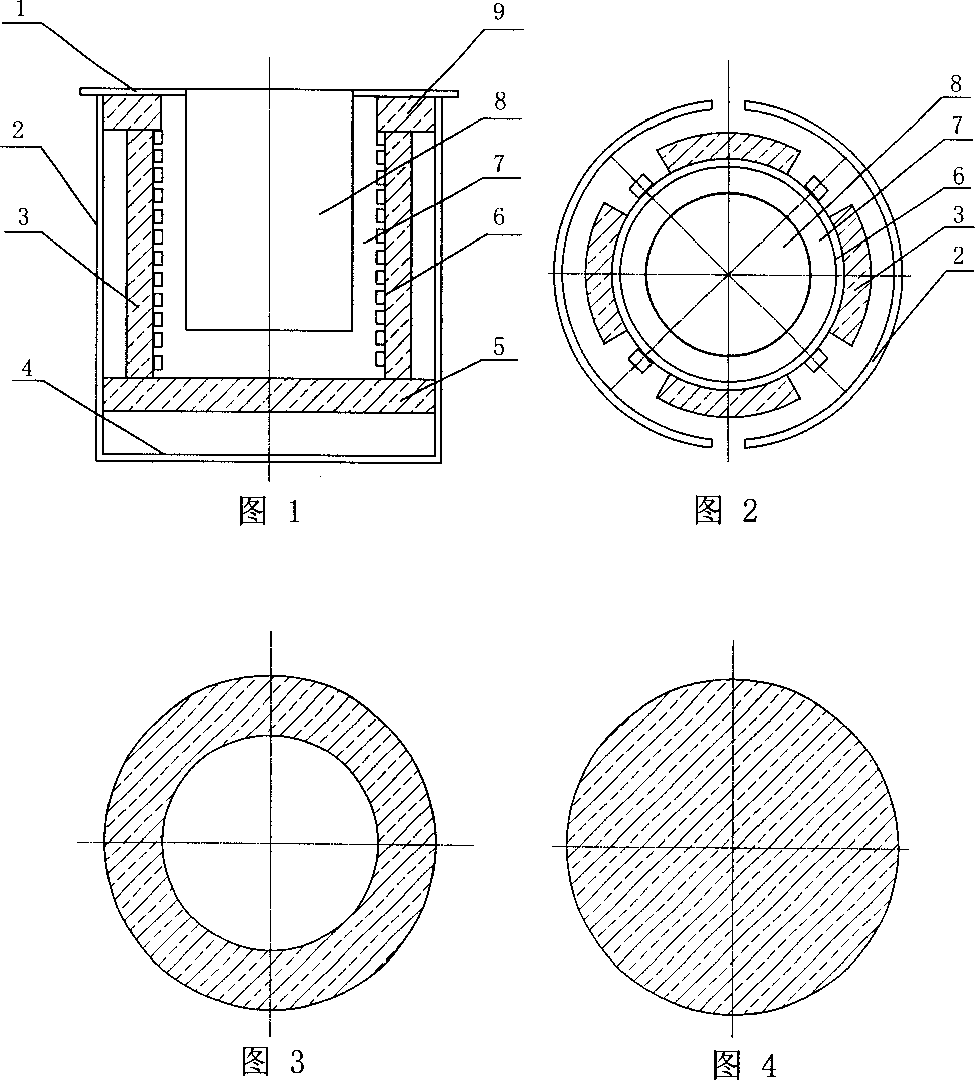
[0018] The present invention will be further described in conjunction with the accompanying drawings of the above-mentioned embodiments.

[0019] As shown in the figure, the low-no-load loss intermediate frequency coreless induction furnace of the present invention includes a furnace shell, a melting chamber lining 7 and an induction coil 6, and the induction coil 6 is placed between the melting chamber lining 7 and the furnace shell 2. The outer side of the induction coil 6 is equipped with a magnetic conduction column 3, and the upper and lower ends of the magnetic conduction column 3 are respectively connected to the furnace mouth magnetic shielding plate 9 and the furnace bottom magnetic shielding plate 5. The cross section of the magnetic conduction column 3 is fan-shaped, and its inner side Corresponding to the shape of the induction coil 6 . The furnace mouth magnetic shielding plate 9 is ring-shaped, and its aperture is compatible with the furnace mouth. The raw mater...


PUM


Abstract

The invention relates to a middle-frequency coreless induction furnace with low no-load loss, applied in metallurgical and casting industries, comprising furnace shell, furnace lining in melting room and induction ring. The induction ring is set between furnace lining in melting room and furnace shell and on the outside of induction ring guiding magnetic pillar is set. Two ends of the guiding magnetic pillar are connected with guiding magnetic mask plates at the fire port and the bottom respectively. The guiding magnetic pillar and mask plate are made of soft-magnetic ferrite, or guiding magnetic iron powder or soft-magnetic material with high resistance, which are provided with high guiding-magnetic ratio and low loss under higher-frequency magnetic field, by sintering and bonding. The guiding magnetic pillar is set between furnace shell and induction ring and relative guiding magnetic mask plate is set between the furnace bottom and hole. Alternation magnetic flux through the furnace shell is little so as to decrease the no-load loss of furnace greatly and because the guiding magnetic pillar and mask plate made of soft-magnetic ferrite, or guiding magnetic iron powder or soft-magnetic material with high resistance has little swirl and magnetic hysteresis loss so that no-load loss of furnace is decreased furthermore and electric power usage and furnace efficiency are improved.

Description

technical field [0001] The invention relates to an improved intermediate frequency coreless induction furnace, which is used in metallurgy and foundry industries. Background technique [0002] In the traditional coreless induction furnace structure, the magnetic flux of the intermediate frequency induction coil forms a closure along the melting zone in the furnace and the external magnetic circuit of the induction coil and the electric furnace shell. The induction current is generated by changing the magnetic flux. Although the steel-shell electric furnace with large capacity is equipped with an external yoke made of silicon steel sheets, the manufacturing process of the yoke is very complicated, and the magnetic flux of several hundred Hz is also in the iron core. The eddy current is generated on the yoke. The eddy current and hysteresis loss of the silicon steel sheet yoke make the no-load loss of the electric furnace larger. The yoke itself also needs water cooling, and t...

Claims


Application Information

Patent Timeline
Patent Type & Authority Applications(China)
IPC IPC(8): F27B14/06
Inventor 邹黎何志兵邹雪
Owner 淄博黎明电器有限公司
Why Eureka
Try Eureka