Tire testing machine and axis misalignment measuring method for tire testing machine

一种测试机、轮胎的技术,应用在汽车轮胎测试、测量装置、轮胎零部件等方向,能够解决温度增加不恒定、温度分布不均匀、难以预料等问题,达到接触面积增加的效果

Inactive Publication Date: 2007-04-25
KOBE STEEL LTD
View PDF1 Cites 10 Cited by
  • Summary
  • Abstract
  • Description
  • Claims
  • Application Information

AI Technical Summary

Problems solved by technology

Therefore, although the effect of local cooling is expected around the coolant passage and the lubricant supply passage, the flow of heat toward the outside of the bearing housing occurs in portions away from the coolant passage and the lubricant supply passage, so that the temperature distribution becomes uneven. Uniform, and thus temperature control applied to the detector becomes difficult
[0022] In addition, the operation of the tire testing machine is high-speed operation or low-speed operation, or long-term operation or short-term operation, and therefore is not constant, and the temperature increase is therefore not constant and unpredictable, and the temperature control of the detector is therefore extremely difficult

Method used


Image

  • Tire testing machine and axis misalignment measuring method for tire testing machine
  • Tire testing machine and axis misalignment measuring method for tire testing machine
  • Tire testing machine and axis misalignment measuring method for tire testing machine

Examples


Embodiment Construction

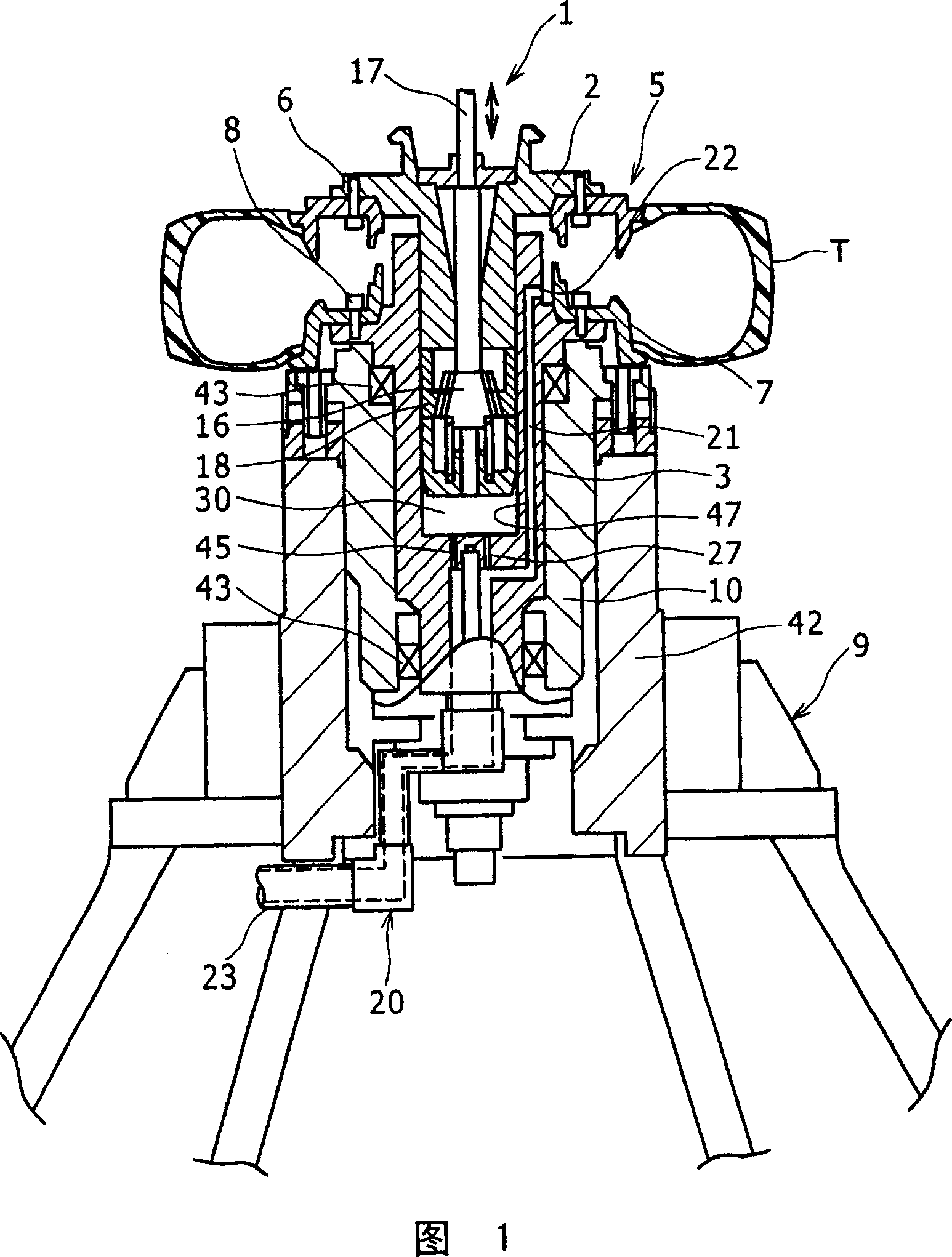
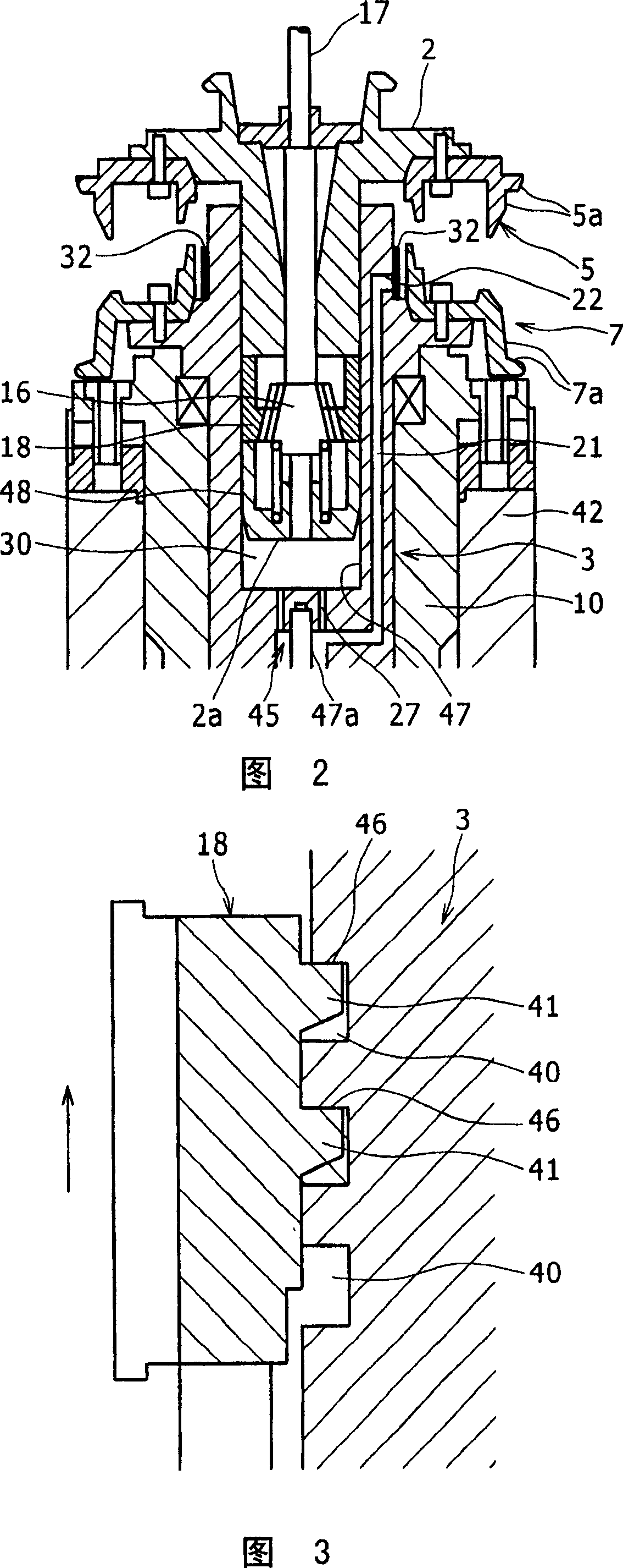
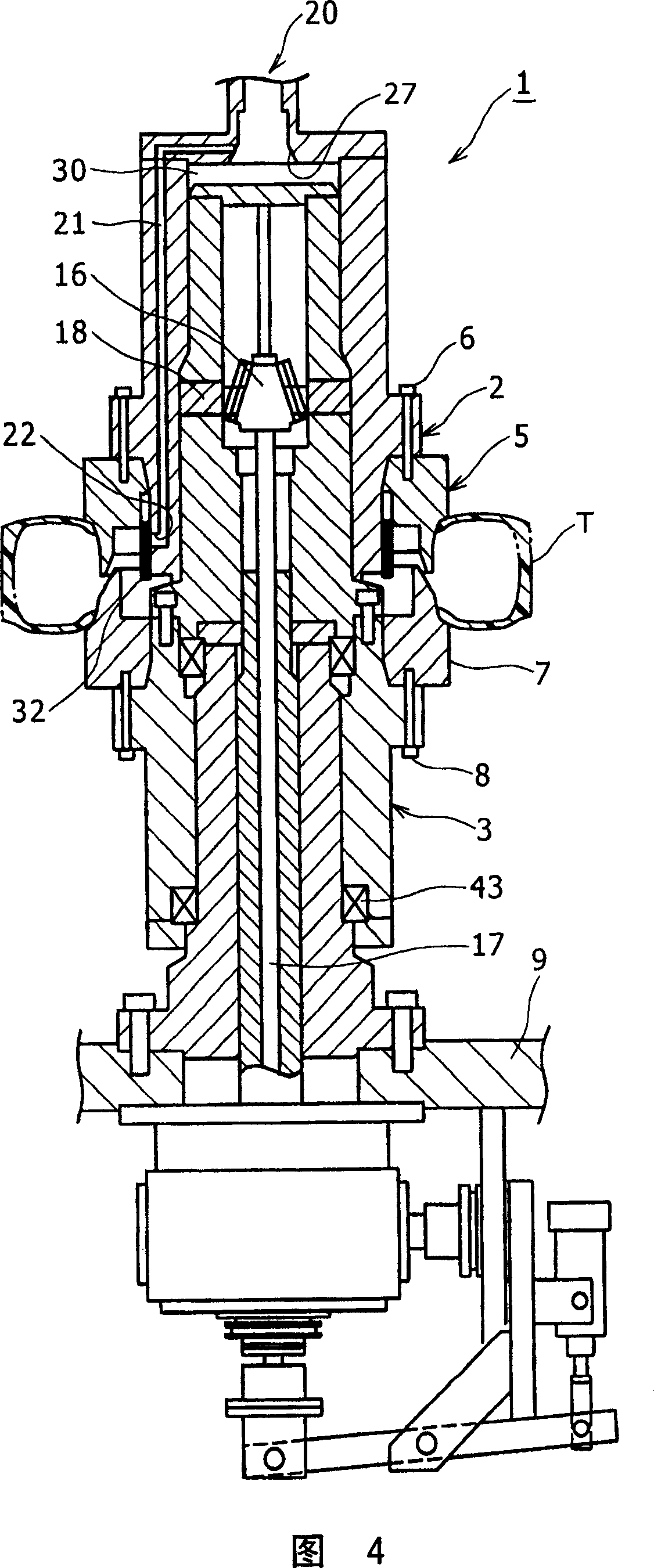
[0059] A description will now be given of a tire testing machine 1 according to a first embodiment of the present invention with reference to FIGS. 1-4.

[0060] 1-3 show a first embodiment of a tire testing machine 1 according to the invention.

[0061] The tire testing machine 1 comprises a tubular first mandrel 3 which is largely open at one end, a second mandrel 2 which has a cylindrical shape and is housed in the first mandrel 3 via the opening, and engages the second mandrel 2 so as to move radially from Lock 18 for extension and retraction of the second mandrel 2 . The first mandrel 3 and the second mandrel 2 are arranged vertically and move relative to each other, the first mandrel 3 is designed as a lower mandrel, and the second mandrel 2 is designed as an upper mandrel.

[0062] The upper rim 5 is fixed to the bottom end portion of the upper spindle 2 by bolts 6 , and the lower rim 7 is fixed to the top end portion of the lower spindle 3 by bolts 8 . The positions ...


PUM


Abstract

Axial engagement means is provided in a tire testing machine. While a tire (T) is not installed, the axial engagement means moves at least either of spindles in the direction to separate them from each other with a lock member (18) engaged with an engaged section (40), the axial engagement means thereby causing the lock member (18) and the engagement section (40) to be engaged in a tightly contacting manner in the axial direction of the spindles. A second spindle (59) has a groove (71) extended in its periphery, in its circumferential direction, and in sliding contact with a lock member (60). The sliding surface between the lock member (60) and groove (71) functions as a receiving section (85) formed in a flat surface so as to receive a separating force between the spindles. A correction device is provided in the tire testing device, and when a spindle (17) rotates, the correction device corrects the gap between an inner ring of a spindle bearing and rolling bodies of the bearing or the gap between an outer ring of the spindle bearing and the rolling bodies. A refrigerant path (219) is provided in a preload bolt (202). The refrigerant path (219) is a hollow region passing that portion of the bolt which corresponds to at least an installation hole (209) of a detector (208), and a refrigerant can be supplied to the refrigerant path (219).

Description

technical field [0001] The present invention generally relates to the technology of a tire testing machine for measuring tire uniformity. Background technique [0002] A tire testing machine for measuring tire uniformity (static or dynamic characteristics of a tire) includes rotating a spindle device holding the tire while the tire is inflated at a predetermined internal pressure and by making a drum contact the outer circumference of the tire held by the spindle device A drum device that applies a rotational force to the surface (for example, refer to Patent Document 1: Japanese Patent Publication No. 2004-28700 or Patent Document 2: Japanese Utility Model Publication No. H6-45239). [0003] However, with this tire testing machine, since the tire is kept inflated, the load generated in the tire testing machine itself cannot be avoided, or the tire is rotated while measuring tire uniformity, and the load degrades the test accuracy. [0004] The present invention has been ma...

Claims


Application Information

Patent Timeline
Patent Type & Authority Applications(China)
IPC IPC(8): G01M1/16B60C19/00G01M1/04G01M1/34G01M17/02
CPCG01M17/021G01M1/045G01M1/04G01M1/16G01M17/02
Inventor 筱本义幸加藤幹雄野中俊克
Owner KOBE STEEL LTD
Why Eureka
Try Eureka